THE ELECTRICS. On this page.
Concealed brake light switch.
The wiring of the bike.
Dipped beam modification.
Notes on modern voltage regulators.
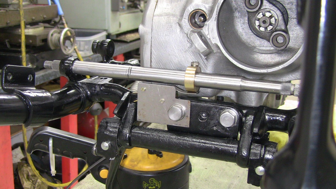
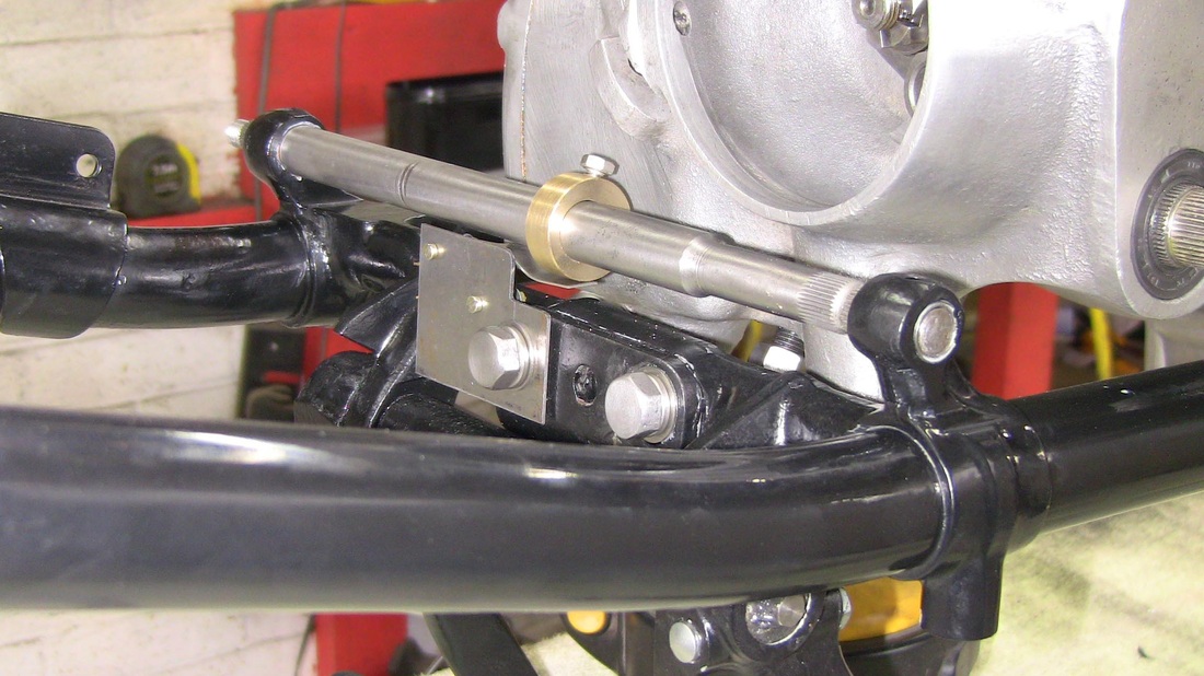
Concealed brake light switch.
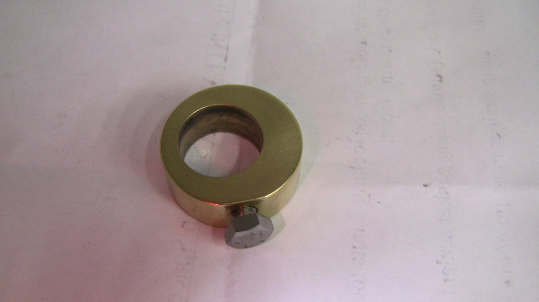
The microswitch is the type used in coin machines. The eccentric is made from brass. The piece of brass was held in the three jaw chuck of the lathe with a small piece of 1/4 inch thick steel between one jaw and the job. Obviously the rotation speed of the chuck has to be low.
The wiring of the bike.
I divided the wiring into three parts.
1. Headlamp to handlebars.
2. Headlamp to control box.
3. Rear mudguard to control box.
All of the wire harnesses are made with PVC thinwall cable, this is rated at 16.5 amps and is the standard wiring as used by car manufacturers. The insulation is thinner but very tough to resist abrasion. It also carries a higher loading compared to the old type cable. Obviously the reduction in the diameter of the wiring harness is a great advantage. This wire comes in a multitude of colours and bi-colours, making harness assembly a simple job.
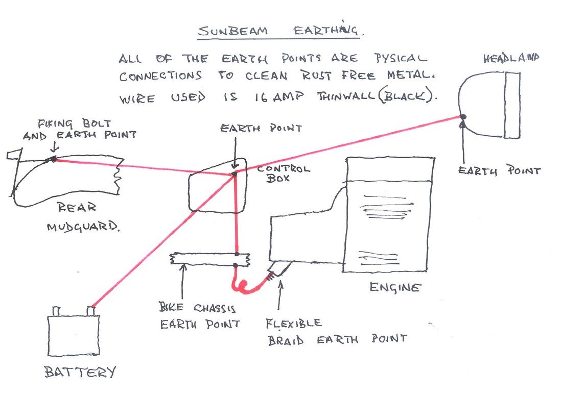
There are three earth points. all connected by copper wire.
Earth point one is 6 mm bolt in headlamp shell.
Earth point two is in main control box. 6 mm stud.
Earth point three is fixing bolt at number plate on rear mudguard.
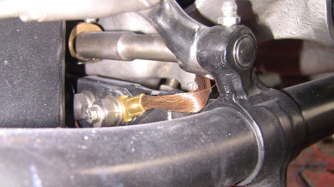
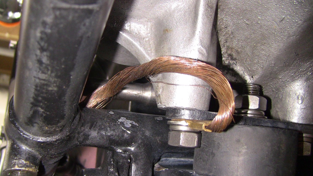
The engine is earthed under the rear rubber mounting with a car type copper braid.
I cut a 6mm slot for the wiring harness in the top tube.
All wiring coming into the control box terminates at a terminal block.
Headlamp : With a digital voltmeter in the centre of the handlebar that illuminates on switch on this makes the ignition light redundant.
I do not have an oil pressure indicator in my car, nor do I need one on the Sunbeam. If the bearings are failing on a bike you will know about it long before the oil light comes on.
I therefore used both headlamp positions for right and left turn indicator repeaters. These are 10 mm High Intensity amber LED's.
I backed the turn indicators up with an audible system that is time delayed. This remains silent on switch on of either turn indicator, after a set period the sounder begins at a low level to sound, gradually increasing to a high level. This delay period is variable and is custom preset by the rider.
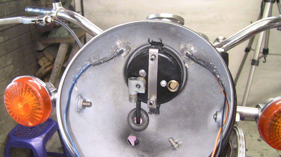
Amber turn repeaters. LED's glued in with hot glue gun. 6 mm earth bolt shown.
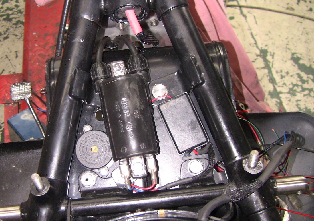
Sounder on left and it's control box on right. Photo shows wiring exiting from frame top tube.
|
|
Engine earthing .
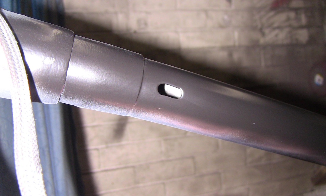
6 mm slot for wiring.
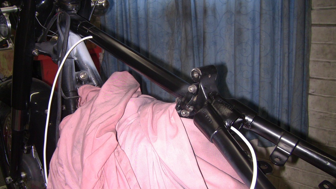
White test cable run through frame.
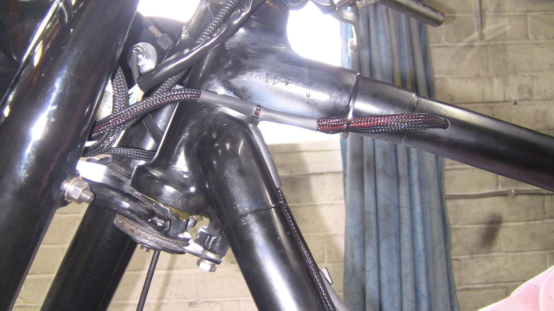
Wiring harness installed.
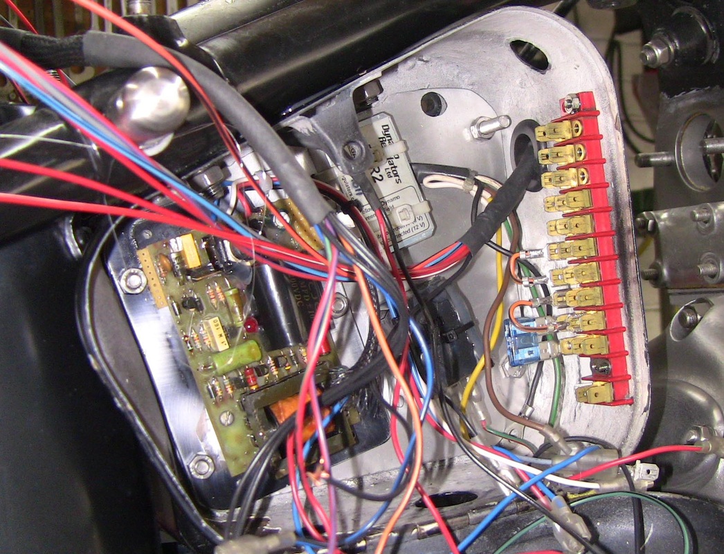
Control box showing common terminal block and 6 mm earthing stud. Also shown is the DVR2 regulator and cutout unit from www. dynamoregulators.com.
Picture below shows schematic earth points.
Dipped beam modification.
Riding in France requires the bike lights to be on. I have 12 volt electrics.
The battery does not start to charge until 38 mph ( in top gear).
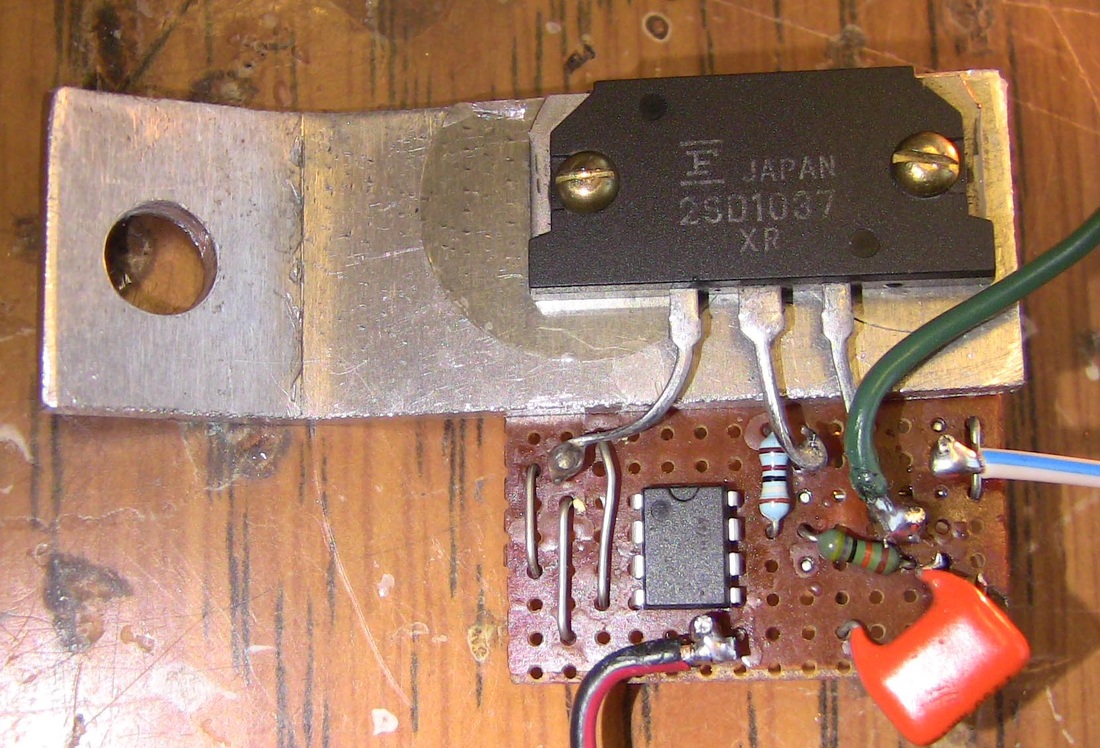
I made up a simple circuit that half's the current to the dipped filament of the 36 watt bulb. The bulb is switched on and off at 100 times a second so the current drawn is 1.5 amps as against 3 amps. The main beam is left at 36 watts.
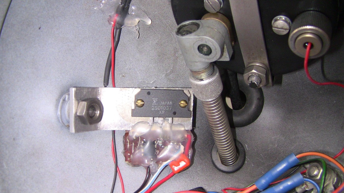
The switcher is shown below. The unit fits neatly into the headlamp shell.
Notes on modern voltage regulators.
It really is an essential part of the modern motorbike to have a reliable battery. The sealed for life or 'gel' battery is light years ahead of the old lead acid battery. Having said that these batteries need to be charged properly and accurately. This is where the modren solid state regulator comes into its own. If the generator is a Lucas dynamo as fitted to Sunbeams I can only recommend the DVR2 regulator available from Dynamo Regulators Ltd ( www.dynamoregulators.com ). The DVR2 is dual voltage 6 or 12 volt and is both negative and positive earth. I cannot recommend this unit highly enough and is an essential when fitting any electronic units to a bike such as an electronic ignition system. Relying on the old electromechanic regulator is most unwise with a sealed for life battery. The Lucas dynamo if left unregulated will increase the output voltage as the revolutions rise and can reach 30 plus volts. This will damage a 'gel' battery and destroy an electronic ignition unit instantly.