Engine speed ignition system. A success story that never completed.
After the initial experiments with the rotating magnet, I decided to go ahead with a working system. I purchased a pickup coil and matching Boyer Bransden electronic ignition unit with electronic advance/retard. The Sunbeam only requires one pickup coil and magnet as the rotor spins at engine speed. The rotor is exactly the diameter of the iron centre of the dynamo. I have made the rotor from brass. This gives a full non magnetic flat surface to the dynamo for rotational stability. The rotor is also balanced. The dynamo centre bolt has the hex head drilled and tapped 5 mm only two thirds of the depth. This is to minimise any strength reduction in the bolt.
The original dynamo end cap is used to mount the aluminium stator location plate. The stator plate is a circular piece of printed circuit board with the pickup coil and the output wires soldered to it. The Boyer Bransden ignition unit is mounted in the battery box. I twisted the two wires from the stator plate in a hand drilling machine. This is to minimise electrical noise in the wires running along the frame bottom rail to the battery box. This has proved successful in that the engine runs very smoothly without any misfires.
Setting up the ignition timing is not a problem. The Sunbeam engine is very softly tuned with relatively low compression amd very mild valve overlap, so we are not looking for Brands Hatch performance.
To time the engine,I started at top dead centre on the flywheel mark. Now I advanced the engine 20 degrees by putting it in top gear and turning the rear wheel backwards so the pistons had gone down the bores by 5/16th of an inch. This was a good starting point. I lined the magnet and pickup coil by eye midpoint in the adjustment slot. On kicking the engine over I noted any kickbacks or spitting. Non occurred and the engine started easily. When warmed up I adjusted the stator plate in it's slots for a nice steady slow tickover exactly as it had been with the distributor.
Riding the bike : The bike ran noticeably smoother with a better response to the throttle. Pulling up a hill gave a smoother flow of power compared to the old mechanical advance system. Obviously until the system is fully proved I will leave the mechanical distributor installed but not connected.
Many thanks go to Kirby Rowbotham for his technical expertise in this project. The pickup coil and ignition unit can be obtained in both six volt and twelve volt posive and negative earth from his company. He can be contacted at www.kirbyrowbotham.com or by telephone 01889 584758.
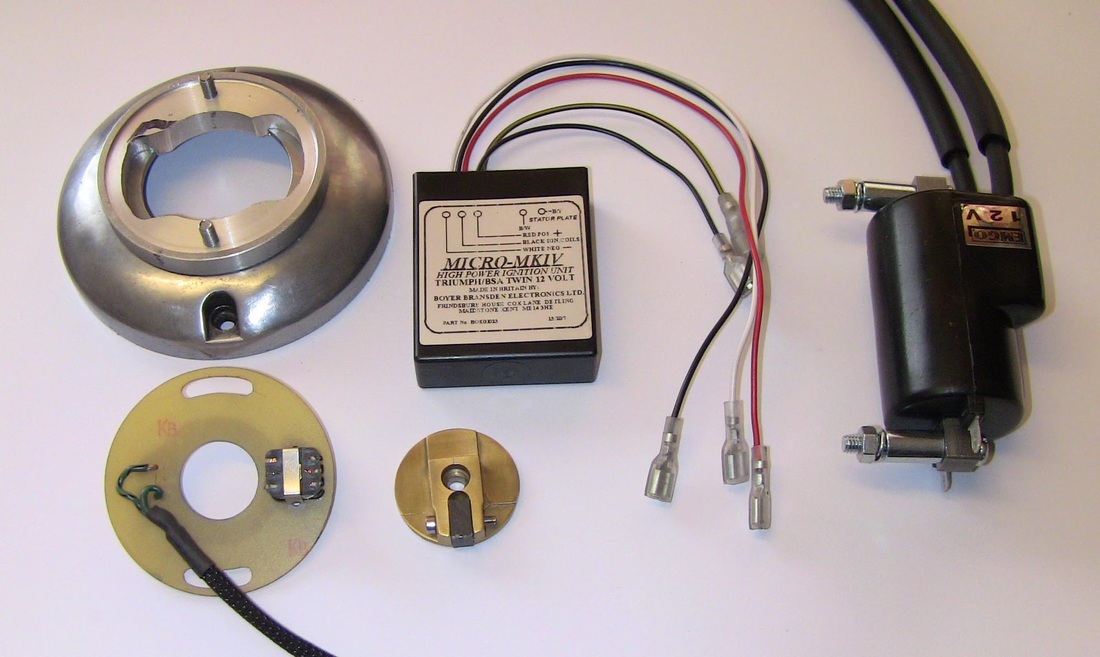
Complete parts for the job.
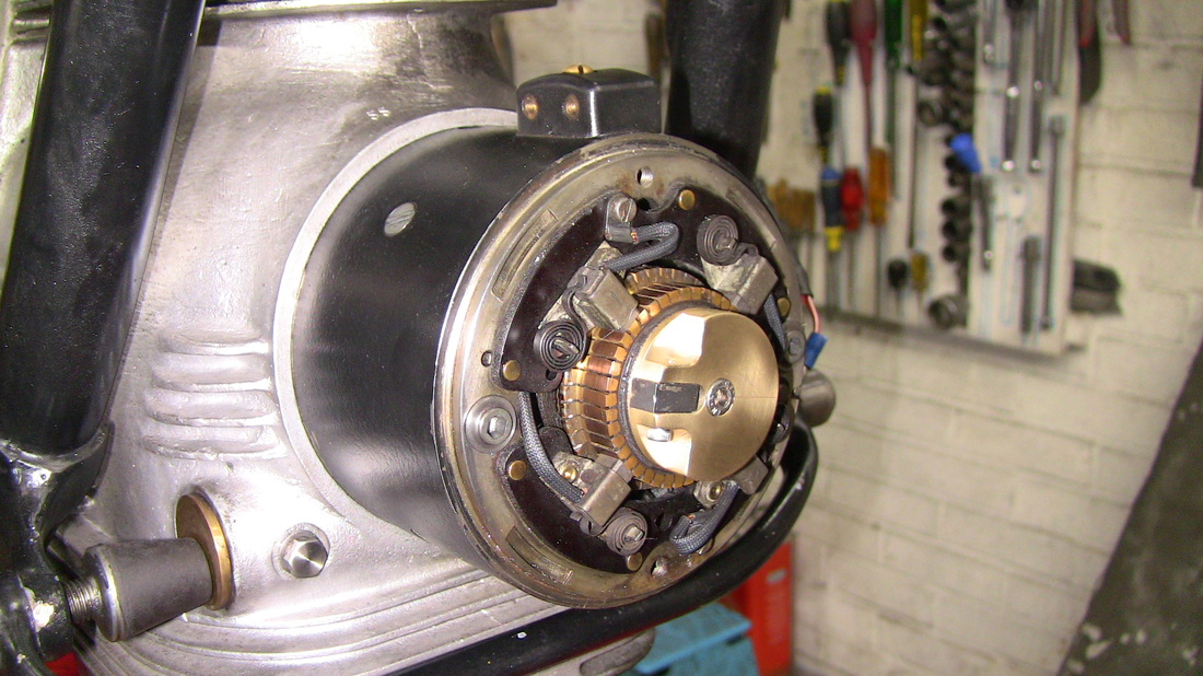
Magnetic rotor mounted on dynamo.
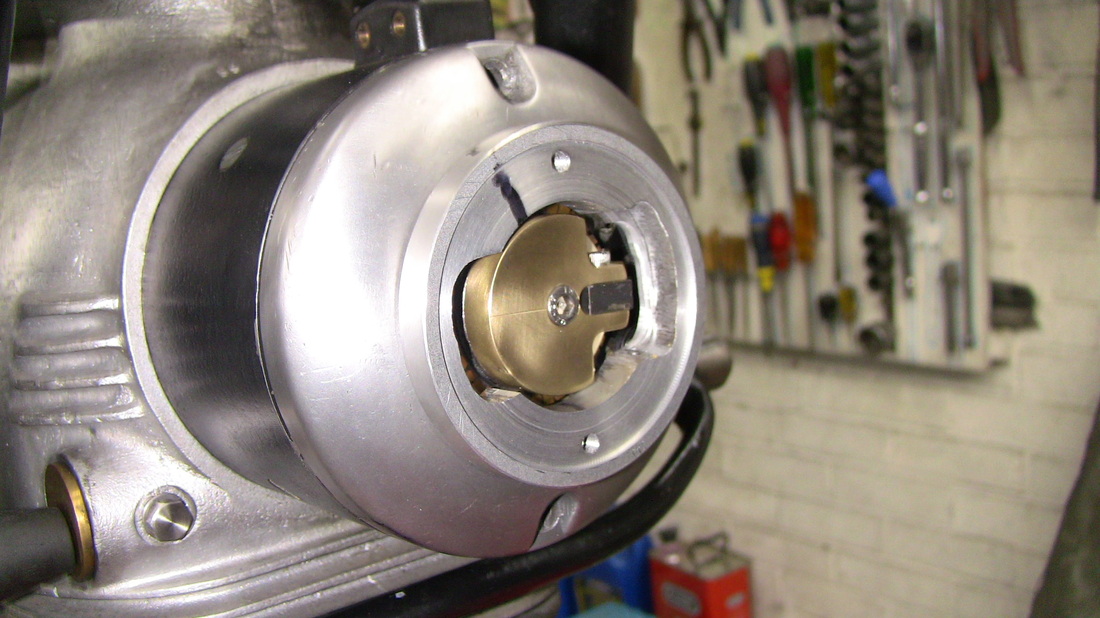
End cap with mounting plate.
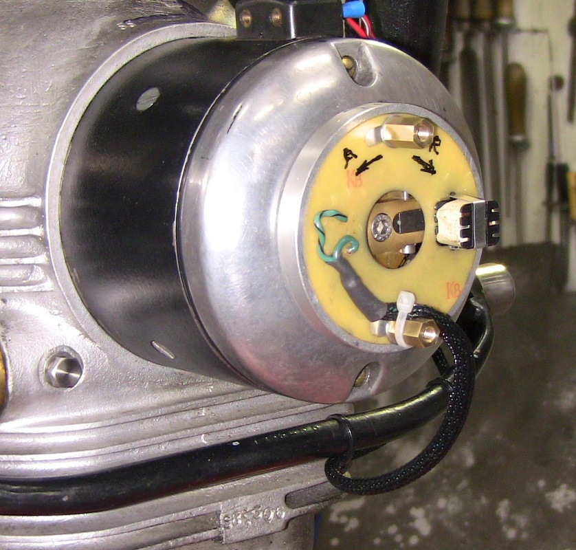
Pickup stator plate installed.
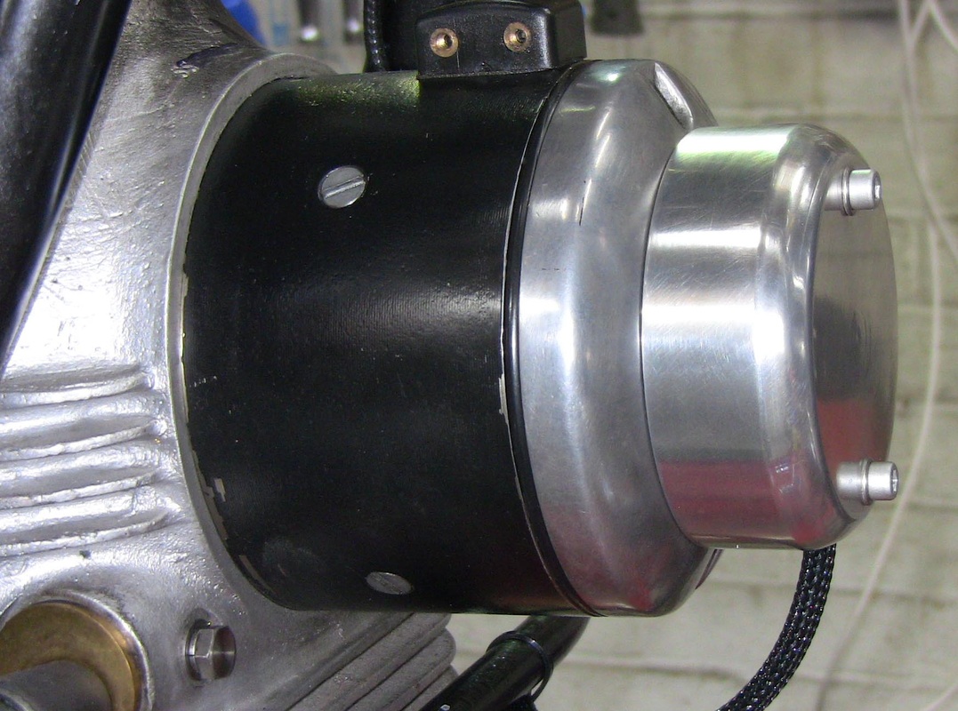
Finished job with cover installed.
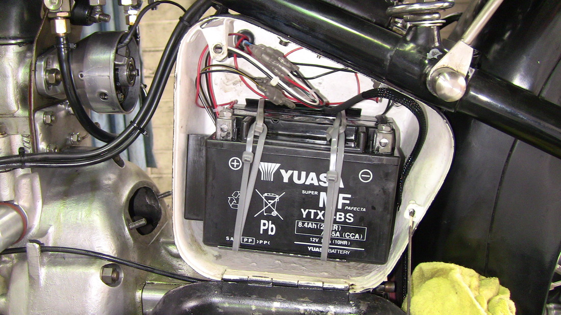
Ignition unit fitted next to battery.
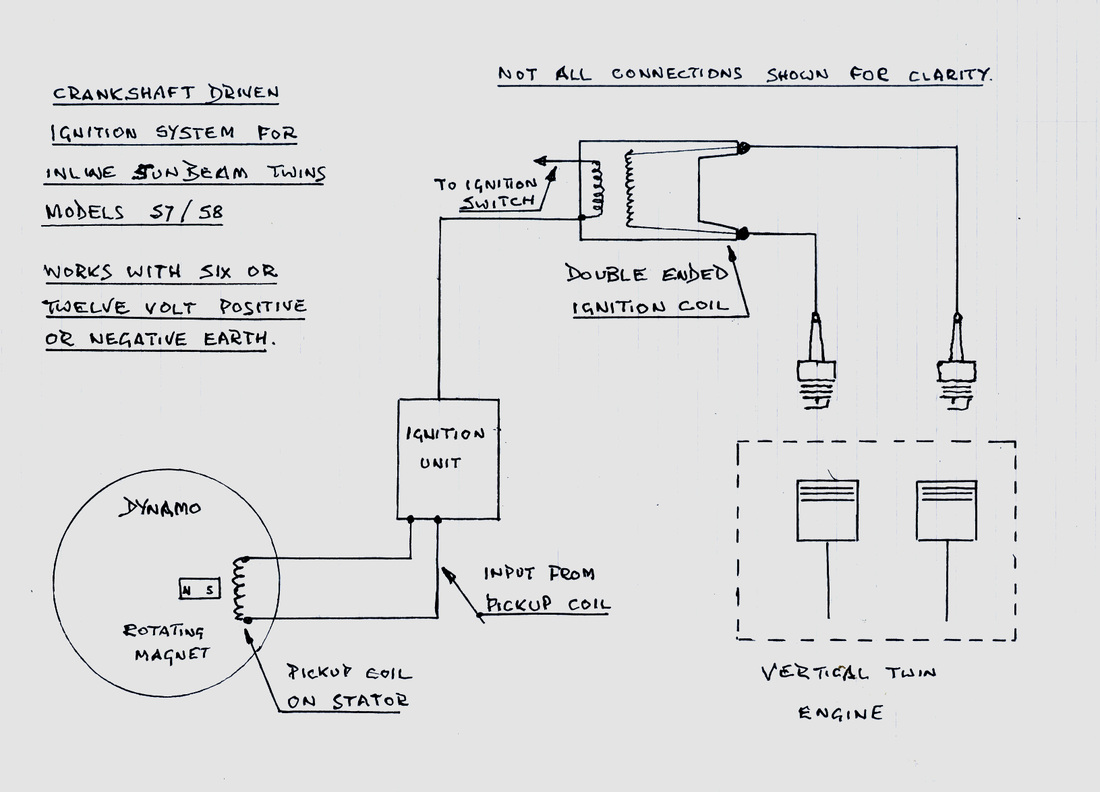
This is the wiring diagram. Note the distributor is no longer needed.