HOW TO PAGE. How to change kickstarter spring.
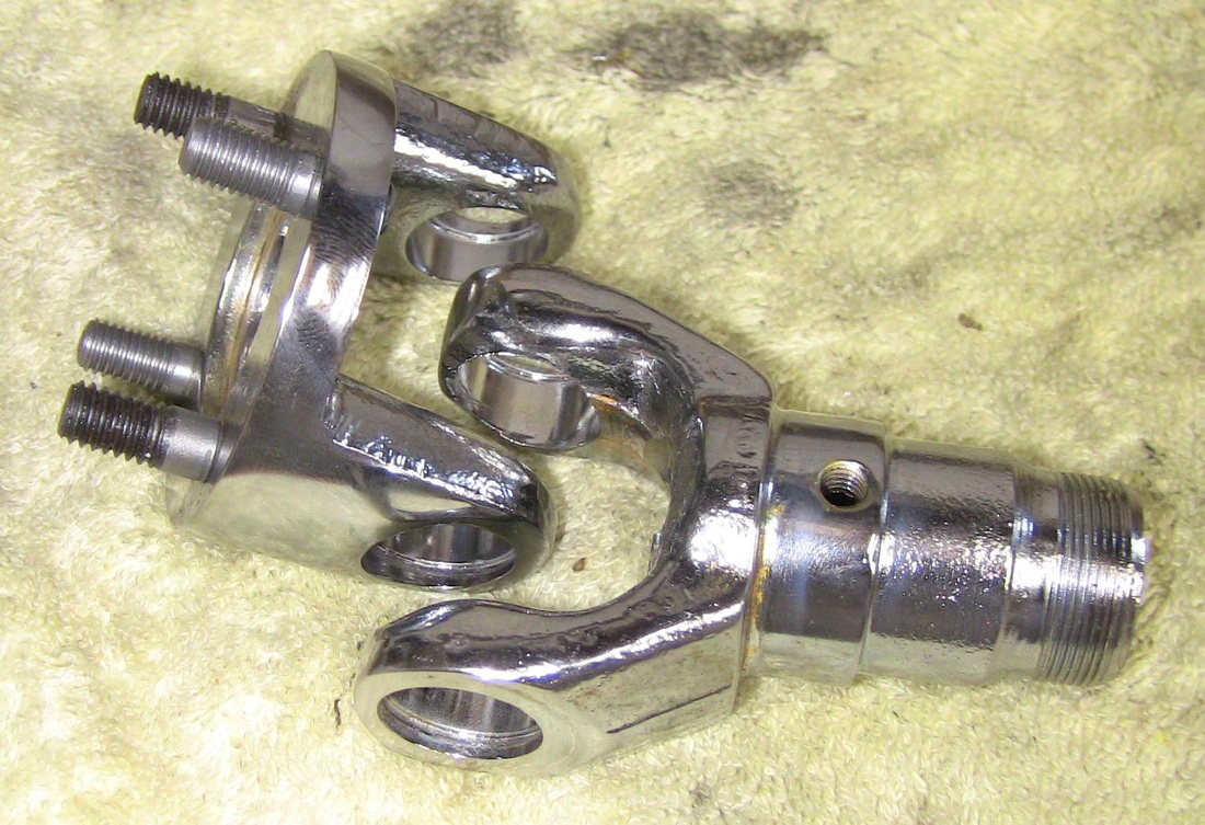
How to rebuild Hardy Spicer. ( universal joint ).
How to make a BSA fork puller.
How to change BSA fork oil seals.
How to lift off a stuck cylinder head.
How to renew petrol tap corks.
How to dismantle and reassemble rear spring boxes.
Kickstarter spring.
Drain gearbox of oil.
Remove small tool box ( two bolts internally ).
Remove left hand footrest. Remove brake pedal.
Remove gearchange pedal and kickstarter pedal.
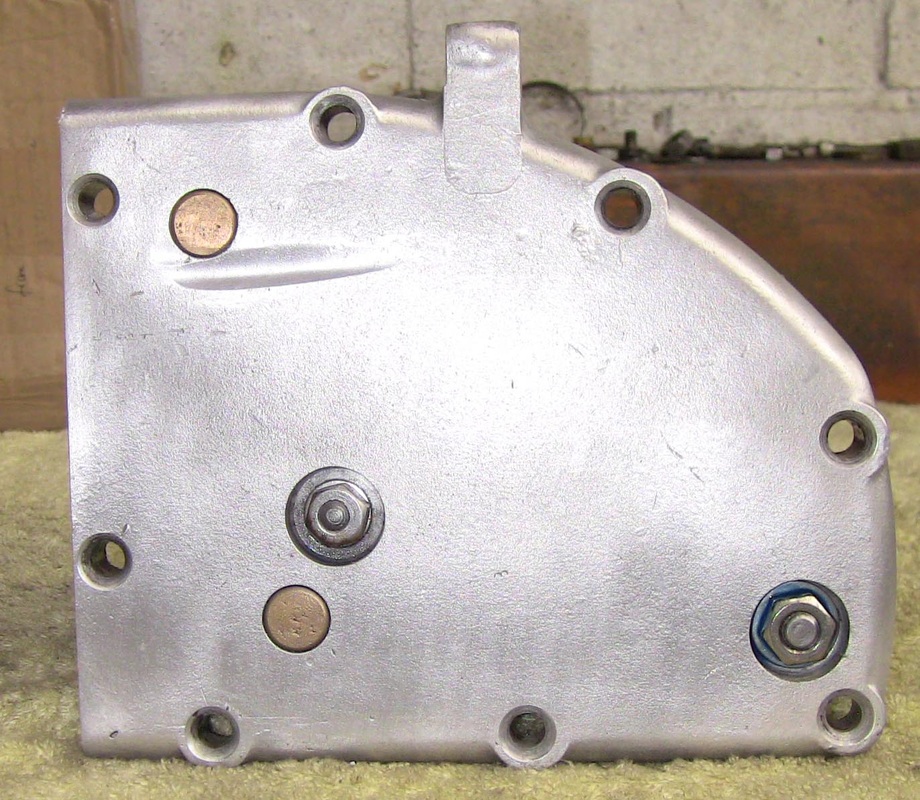
Remove countersink screws from flat side of gearbox. Picture 1 below.
Now slide complete side of gearbox straight out. This will include the gearchange and kickstarter shafts but all gear internals remain intact inside the main body of the gearbox. Remove the 3/8th BSF nut at the lower right. This is the large stud which is the stop for the kickstarter quadrant. Remove the two small nuts holding the complete shaft assembly. Clamp the shaft in a soft jawed vice and prize off the c ring. When purchasing a new kickstarter spring you will also need a circlip to replace the c ring.
The following slide show should hopefully show how straight forward the replacement of the kickstarter spring is. Do not omit to fully tighten the 3/8th BSF bolt on completion. A new side plate gasket to complete the job.
The following slide show should hopefully show how straight forward the replacement of the kickstarter spring is. Do not omit to fully tighten the 3/8th BSF bolt on completion. A new side plate gasket to complete the job.
Rebuilding a Hardy Spicer.
How to make a BSA/Sunbeam fork puller. ( Very cheaply )
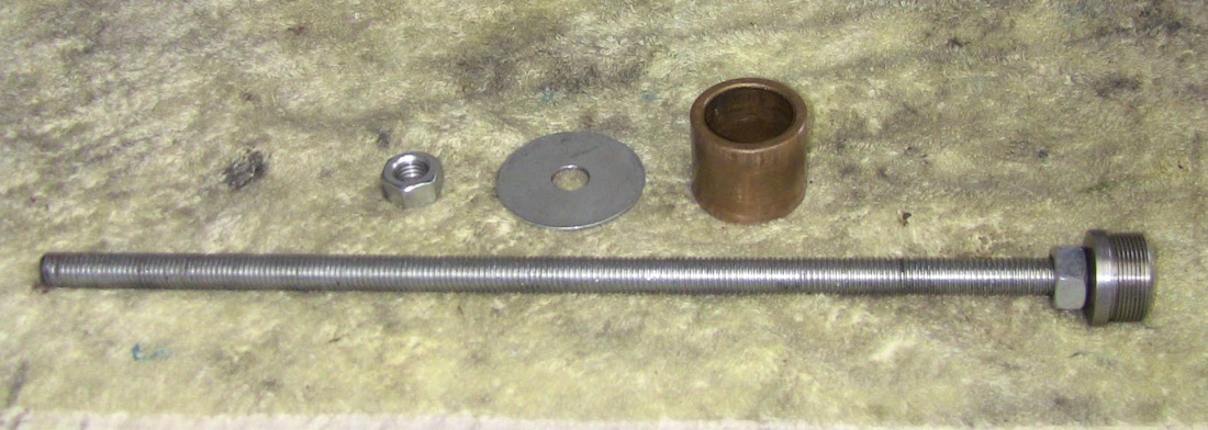
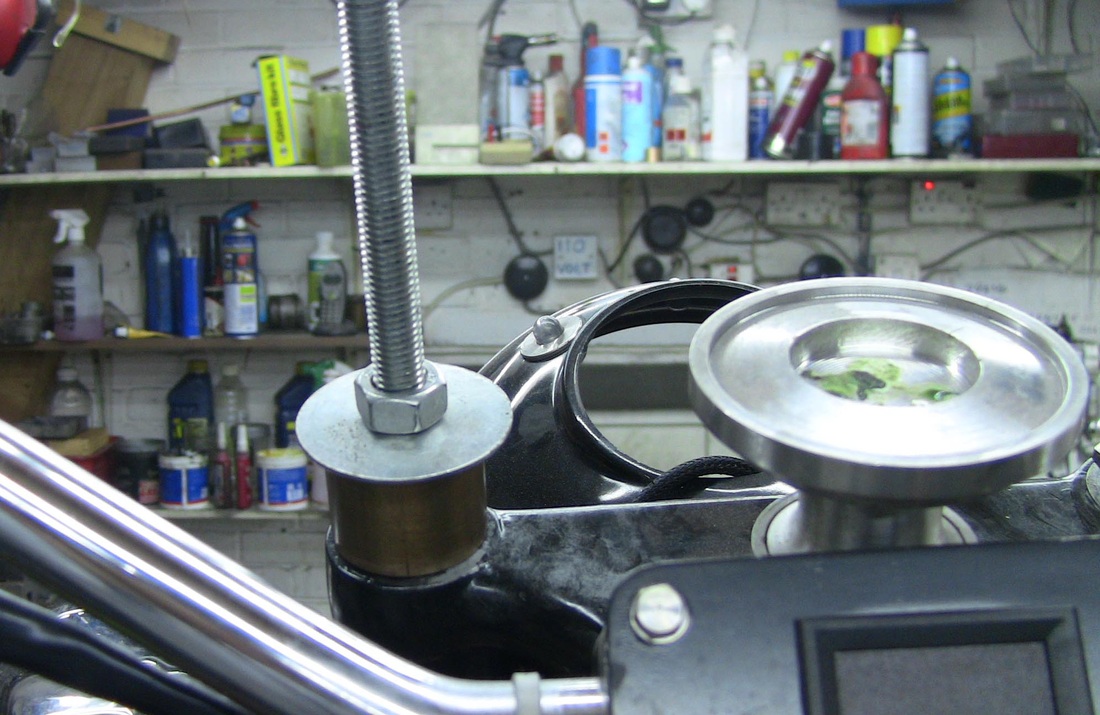
The picture below shows the component parts.
1 off 12 inch length of 12 mm studding.
3 off 12 mm nuts.
1 off BSA fork top nut.
1 off 12 mm penny washer
1 off old BSA fork bush.
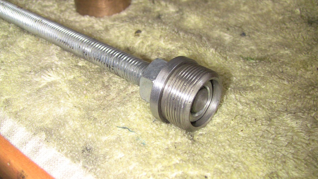
The BSA fork top nut is drilled in the lathe with a 12mm centre hole.
The hexagon is turned off in the lathe such that the nut will comfortably pass through the hole in the top yoke where the fork stanchion fits. The modified top nut then is clamped between two 12 mm nuts as shown in picture below.
The hexagon is turned off in the lathe such that the nut will comfortably pass through the hole in the top yoke where the fork stanchion fits. The modified top nut then is clamped between two 12 mm nuts as shown in picture below.
How to change the BSA/ Sunbeam fork oil seals.
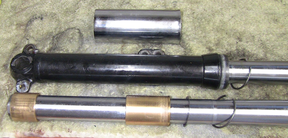
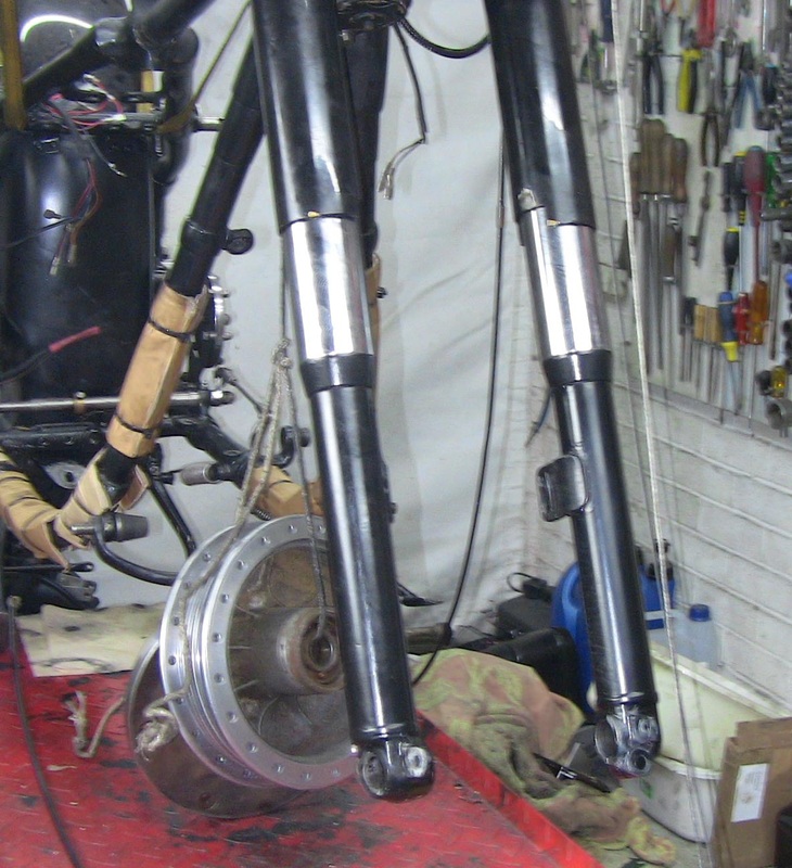
Picture below shows the forks, ( partially dismantled ) at the top is the oil seal holder.
The steel stanchion has the fixed bronze bush at the bottom and the sliding bush in the middle with the steel shim and c locking ring.
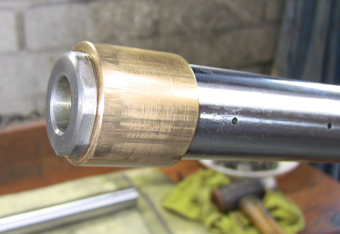
Remove the large four sided nut holding the bottom bush on. Slide off the two bushes and the shim and locking ring. Slide off the chrome oil seal holder.
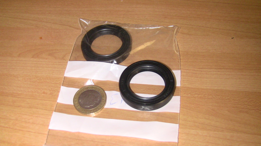
New oil seals
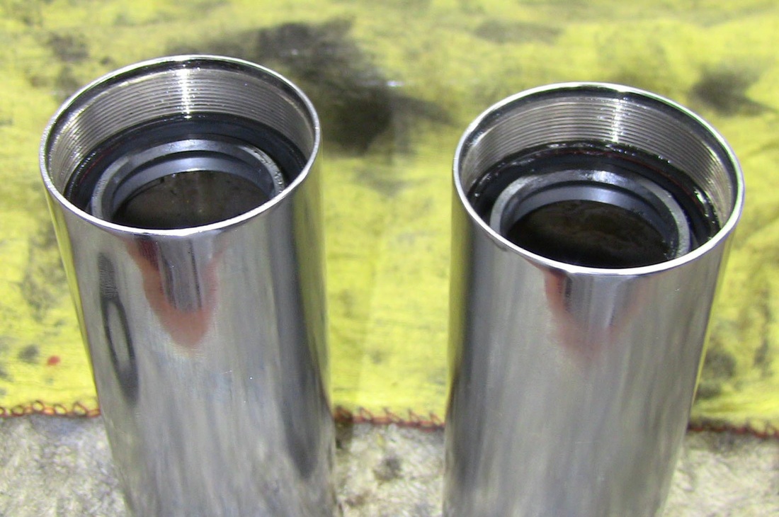
Push the new seals into the holders just enough to see a couple of threads ( as below )
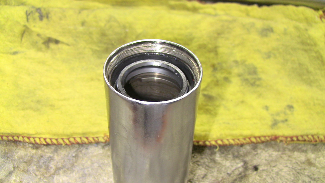
Then screw the holders onto the fork tubes finally pushing the oil seals fully home. This method ensures the oil seals are fully up against top of tubes with no void where oil can collect. ( picture below ).
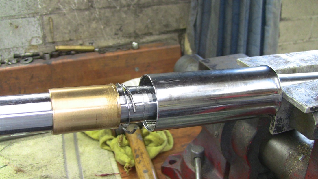
Grease the oil seals and fit the assembly from the bottom followed by the c ring then the shim, sliding bush and finally lower fixed bush and locking squared nut. Do not put oil seals from top of stanchion tube. The stanchion tube is larger in diameter at the top and will stretch and ruin oil seal ( see picture below )
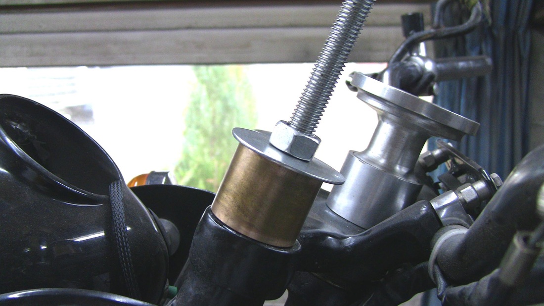
Reassemble the fork legs, the c ring is a bit tricky to get into the groove. I am told this was an apprentices job in the BSA factory. So keep trying and eventually they do pop in. Then using the fork puller as described above pull the stanchions up into the fork yokes. Tighten the clamp screws and remove the puller, fill the forks with the correct amount of oil and refit top caps.
Finished job !
Removing a stuck cylinder head.
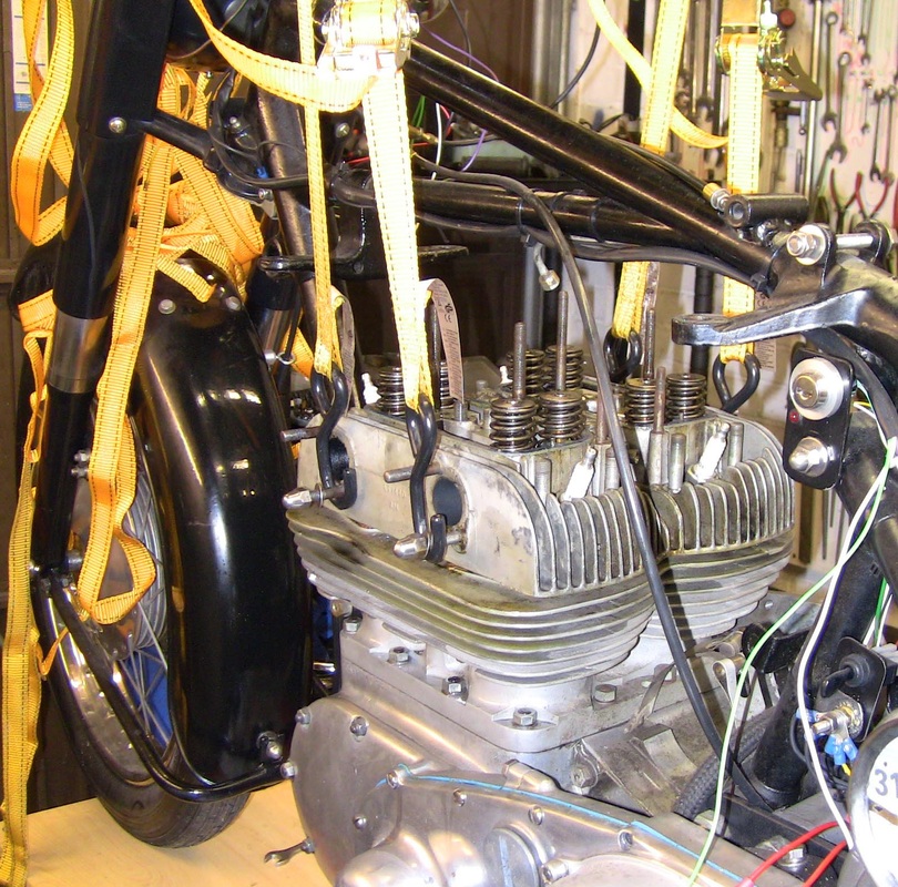
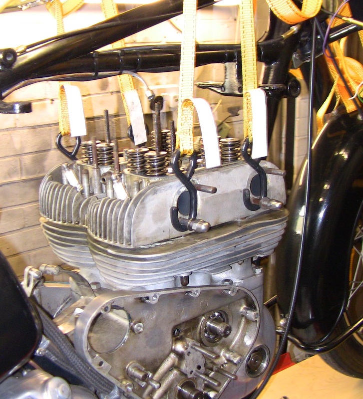
The method described below should apply to most engines that have the cylinder head at the top. The following two pictures show the method as applied to a four cylinder Ariel engine. Using gravity as the force to separate the head from the block has several advantages. It does away with broken fins ( both aluminium and cast iron ) Mating surfaces wrecked with steel screwdrivers or pry bars !
So remove all nuts and bolts holding the head down. Apply Plusgas or vinegar to studs where possible.
It does not matter if the engine is in or out of the frame. Using rachet straps lift the cylinder head at the strongest points with just enough force that the whole engine/bike is just lifted and all of the weight is on the cylinder head. If the head is reluctant to move keep applying the Plusgas and eventually the gap will increase between head and block. I found that this usually occurs overnight.
In the case of the Sunbeam engine I would suggest removing the camshaft and putting a rope through the bearing holes and connect the lifting straps to the rope.
Renewing petrol tap corks.
New corks available from Draganfly Motorcycles. See recommended suppliers.
Slide show below.
Rear Spring Boxes.
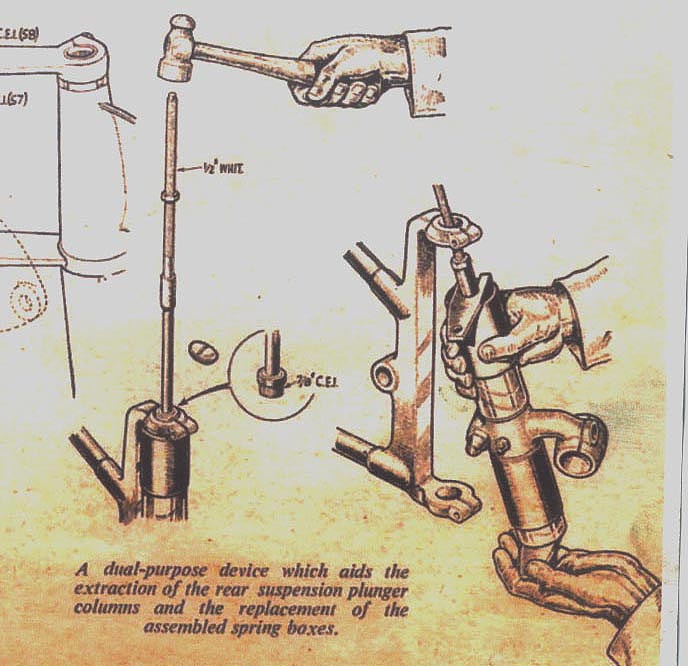
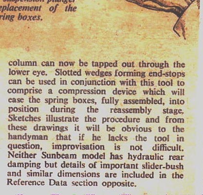
This is an article showing how the Sunbeam chaps disassembled and reassembled rear spring boxes.
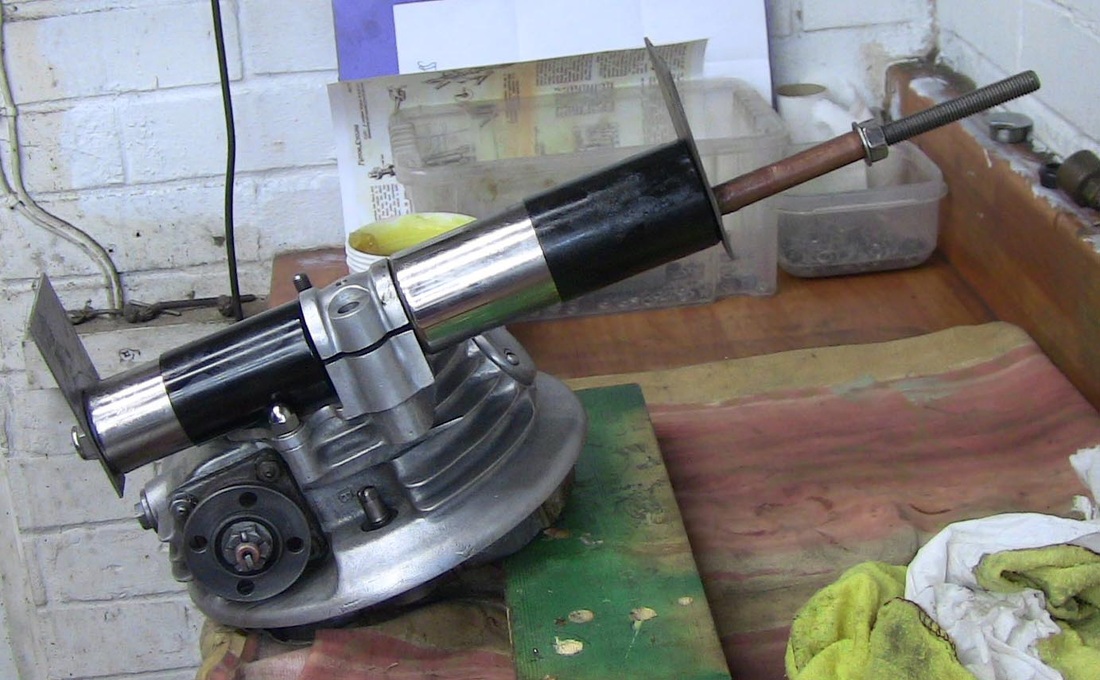
Essentially it consists of two thin steel plates with a slot cut in them. A threaded steel rod ( 8 mm ) Two 8mm thin nuts and standard 8 mm nut.
A short piece of tube to fit over steel rod.
A short piece of tube to fit over steel rod.
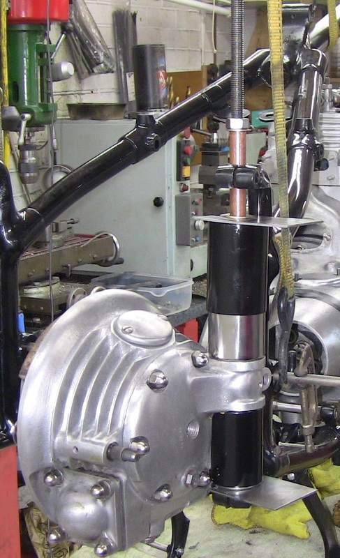
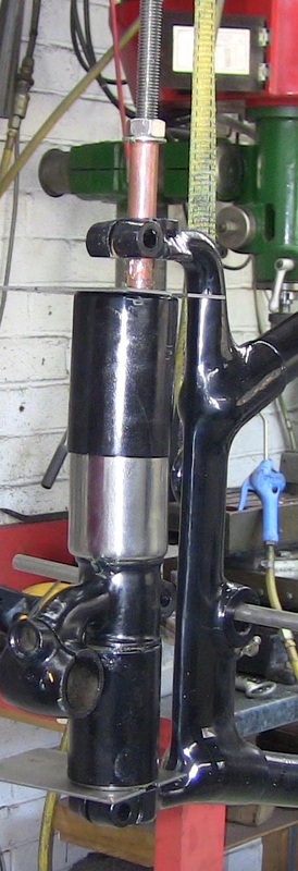
To disassemble the units. remove the clamp bolts and top caps holding the central tube in place . Tap the centre tube down just sufficient to allow the first slotted steel plate to be tapped in between the frame and the spring cover.Now slide the centre tube down followed by the steel rod. At the bottom have the steel plate already tapped into the gap between the frame and spring cover. As the centre tube drops out slide the bottom plate fully home so that the steel rod is centered. With the steel rod now protruding from the bottom fit two thin lock nuts on close to the end as possible.Now slide tube over steel rod followed by nut. Tighten top nut until springs are compressed sufficiently for lower spring box to clear lower frame member.
Some paint damage does occur to the frame and spring boxes with this method.
The picture below shows the spring boxes compressed ready to be lifted out. ( Differential side ) .
Some paint damage does occur to the frame and spring boxes with this method.
The picture below shows the spring boxes compressed ready to be lifted out. ( Differential side ) .
The picture below shows the nearside spring box assembly compressed ready to fit back in the frame.
Picture below shows top nut being released to refit spring box assembly.
