Modifications Page Two. On this page :
Rubber mounted petrol tank.
Handlebar weights.
Steering damper.
Accessing the cylinder head nuts.
Engine mounting brace plate.
Oil feed drillway to camshaft.
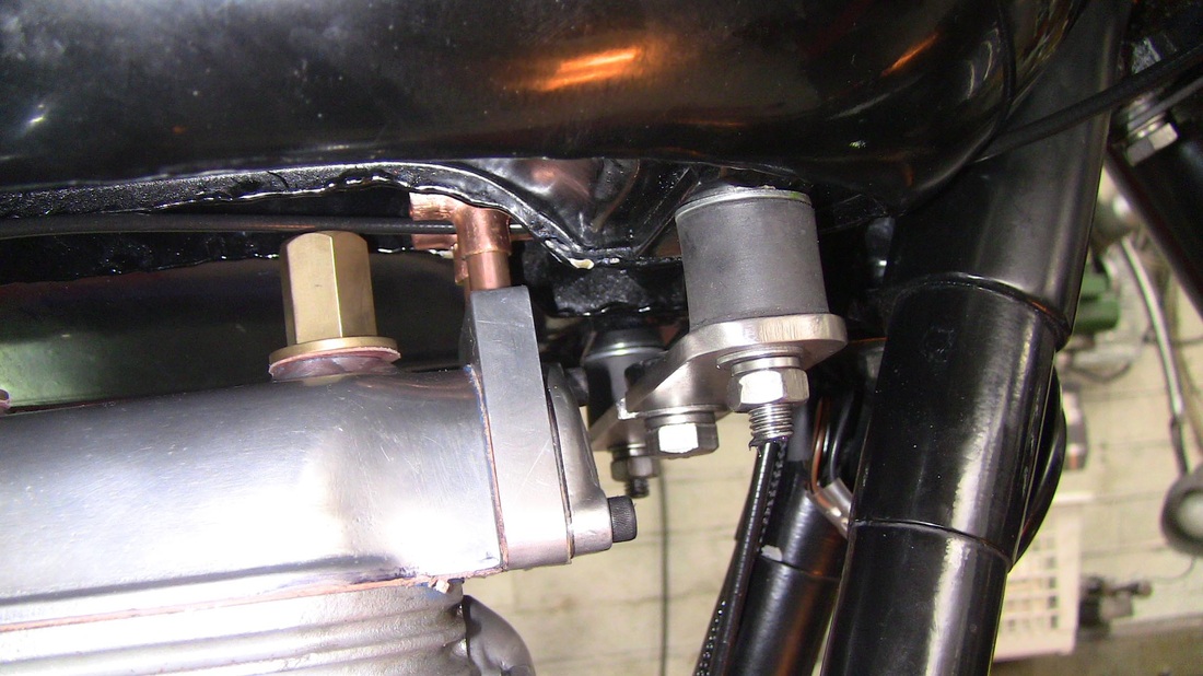
Rubber Mounted Petrol Tank.
Threads had been damaged in petrol tank, new inserts were cut with 8 mm thread. Tank is now mounted on exhaust rubber mounts. The crossbars are flat steel bar.
|
|
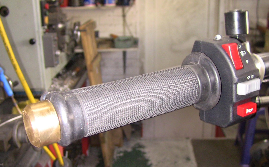
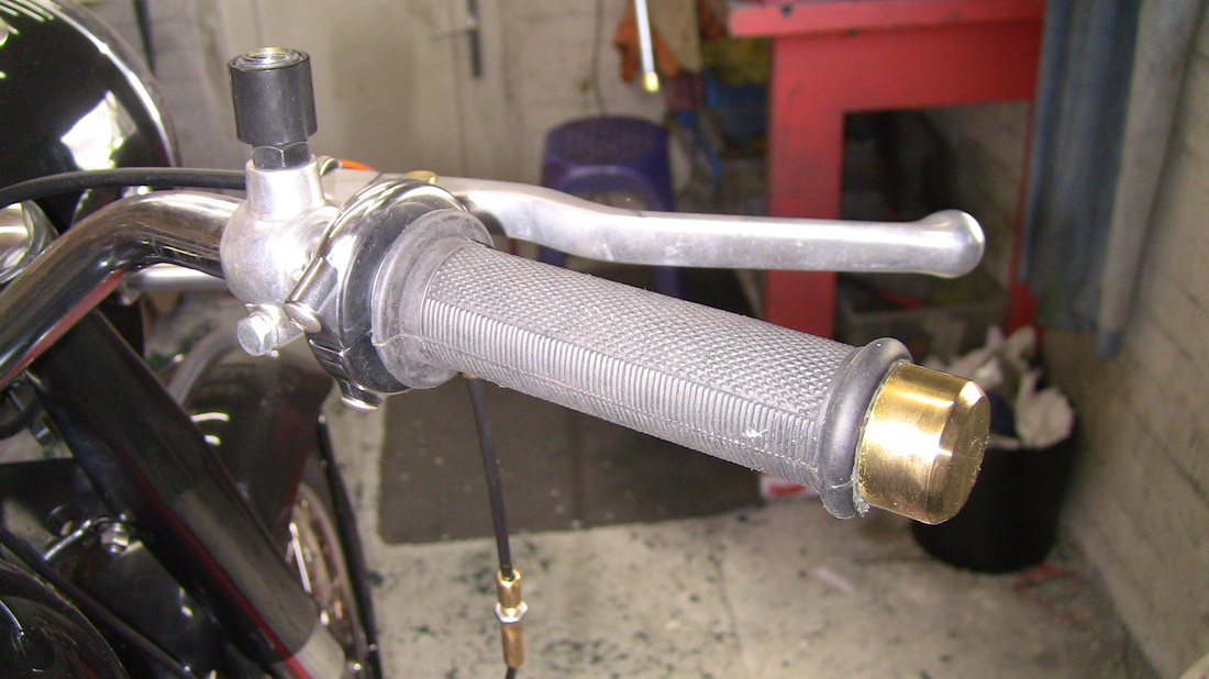
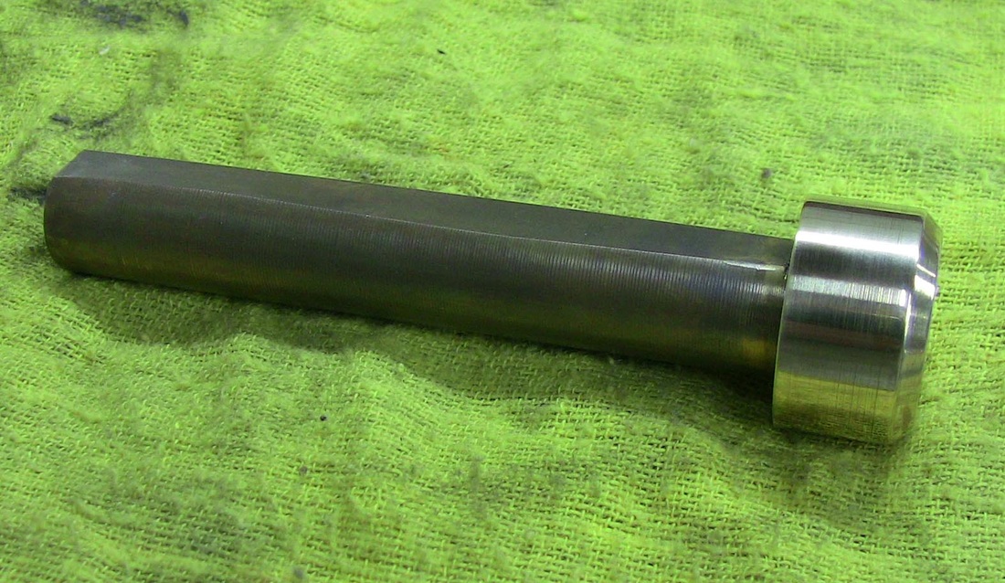
Handlebar Weights.
Two six inch long pieces of brass rod machined to fit inside handlebar. Glued in with silicon sealer. Damps handlebar vibrations.
|
|
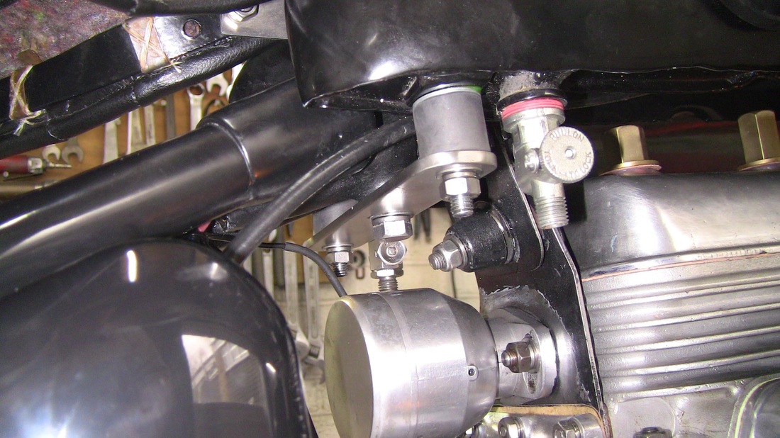
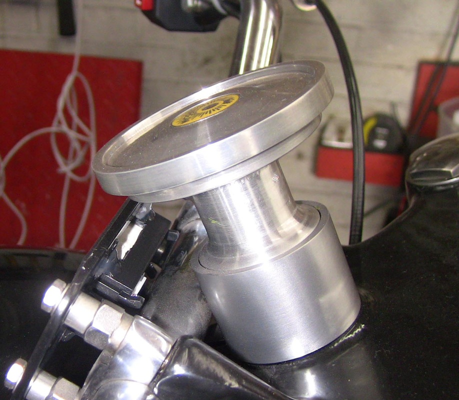
Steering Damper.
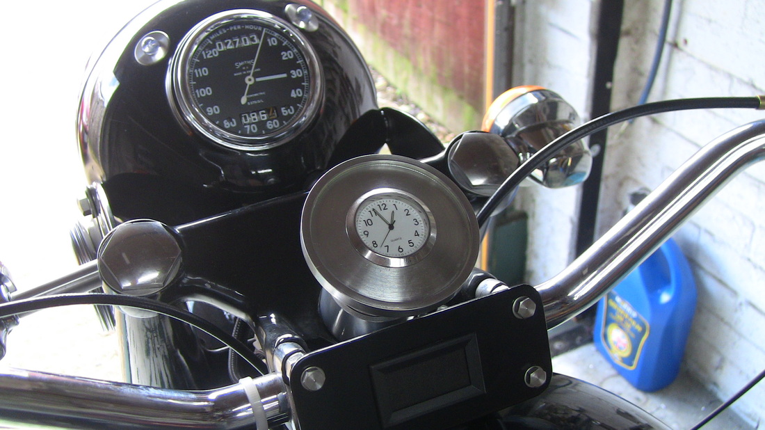
The original bakelite knob was broken. So I was about to replace it with a new one. However, the thought was always there regarding displaying the condition of the battery and the dynamo at the handlebar. I machined an aluminium collar to fit tight on the big chrome locking nut for the head race. ( See first picture). The idea then was to machine a dummy damper knob with a small round ammeter in the centre. The dummy damper knob would be a tight fit in the aluminium collar and held with two grub screws. The two sleeved wires would come out of a slot and into the headlamp shell. It was while I was machining the damper knob I realised a small digital voltmeter mounted central on the handlebar was a better solution to the problem. The damper knob is now fully functional with a small lapel badge glued in the centre. Later a small clock was fitted.
Originally above with a Sunbeam lapel badge.Below with small clock.
Accessing the front and rear cylinder head nuts.
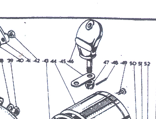
It has been pointed out to me that a mild steel plate called an 'Engine Mounting Brace Plate' must be fitted on the front top engine support lug. Problem is this should be fitted at the same time the cylinder head is fitted. See Plate One of Stewart Engineering drawings, item number 45.
So I had removed the 'cobra head' stud and replaced it with a 3/8 BSF high tensile bolt with the head machined down to a thickness of 5 mm. to allow a 5/16th open ended spanner access to the nut.
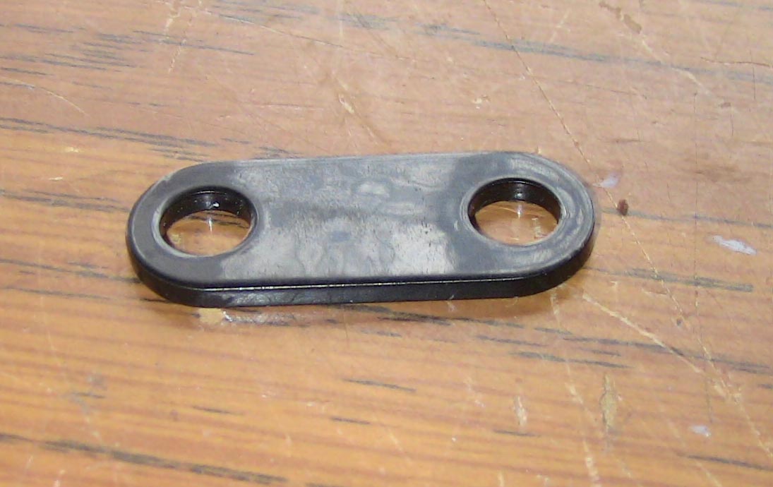
I have made a brace plate from 2 mm thick steel with a slot just wide enough for the cylinder head bolt to pass through. This should spread the load on the front aluminium lug.
Thanks go to Michael Williams for pointing out the missing brace plate.
Tightening the cylinder head nuts frequently and evenly after fitting a new head gasket pays dividends. It is no good tightening the front and rear nuts to breaking point because they cannot be accessed easily after assembly. If the head and block is distorted they must be skimmed. Usually the head is bowed front to back by the aforementioned tightening procedure. This leads to oil seepage from the camshaft feed. No amount of tightening will stop it. I find that if the two surfaces are flat, the rearmost centre small stud is not needed. This makes fitting the rear head nut and washer very easy. A short 5/16th Whitworth spanner can then access the nut in the gap between the battery box and the engine rear.
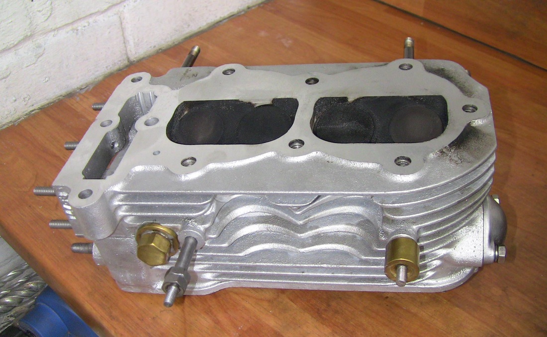
Skimmed cylinder head.
|
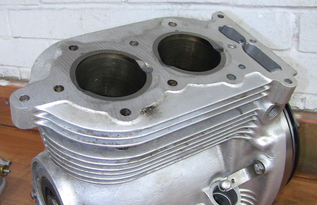
Skimmed cylinder block.
|
|
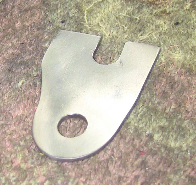
Steel home made brace plate.
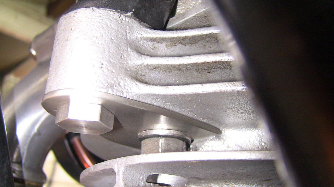
Installed brace plate.
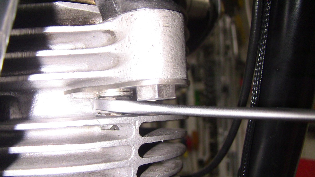
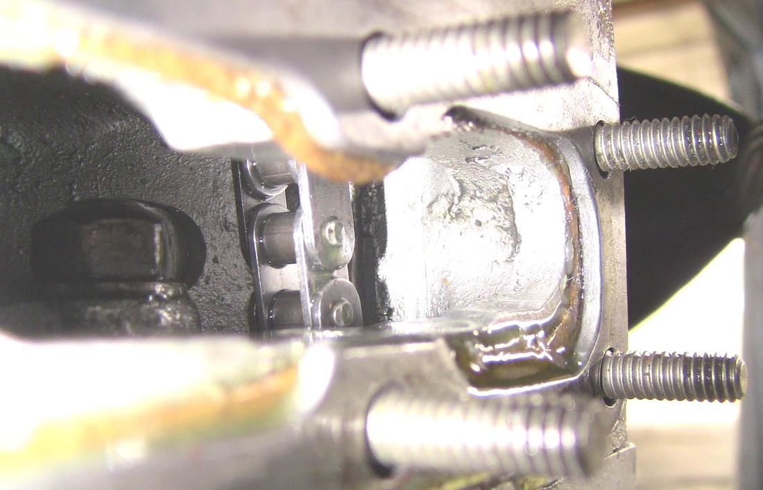
Clearance showing 3/8th BSF spanner on cylinder head nut.
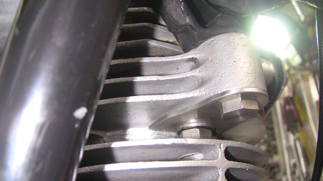
Rear of cylinder head.
Rear cylinder head nut ( actual view )
Rear cylinder head nut ( mirror view )
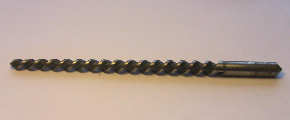
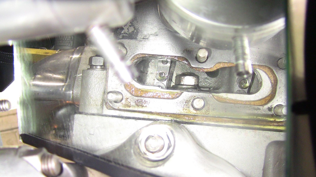
Oil feed drillway in cylinder block and head.
The oil feed drillway in the cylinder block is a different diameter to the oil feed in the cylinder head that feeds the camshaft. I used a taper reamer to enlarge the cylinder head drillway to the same diameter as the cylinder block. It can be argued that the gradual change in diameter reduces the likelihood of the oil seepage past the head gasket. It worked in my case. I would like to see an oil groove in the main bearing of the camshaft so that the oil flow was steady and even. The tapered reamers are used for setting steel taper pins in steel forgings and are readily available in all sizes. Picture below.
The oil feed drillway in the cylinder block is a different diameter to the oil feed in the cylinder head that feeds the camshaft. I used a taper reamer to enlarge the cylinder head drillway to the same diameter as the cylinder block. It can be argued that the gradual change in diameter reduces the likelihood of the oil seepage past the head gasket. It worked in my case. I would like to see an oil groove in the main bearing of the camshaft so that the oil flow was steady and even. The tapered reamers are used for setting steel taper pins in steel forgings and are readily available in all sizes. Picture below.