Putting the engine together.
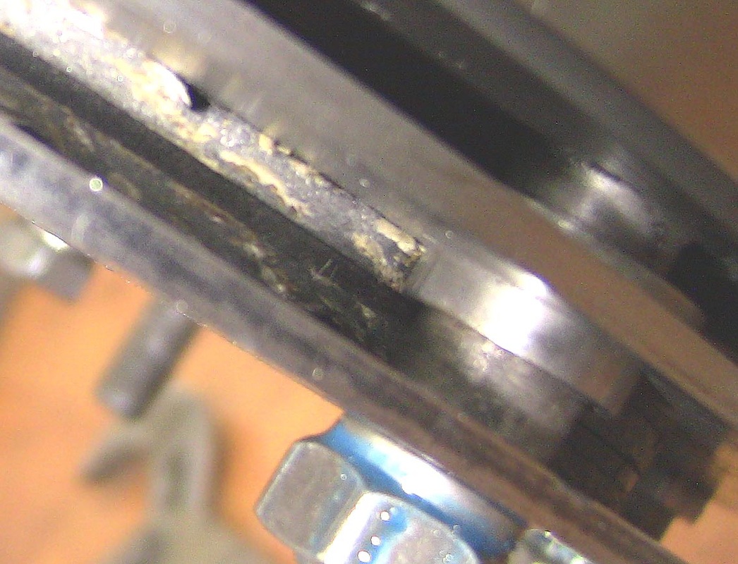
I had carried out a rapid rebuild of the engine in early spring of 2012 when I knew I was going to Normandy in June. The front main bearing in my 1949 engine was a ball type, so I replaced like with like. I ran all summer but the bearing got a bit 'rumbly' and slight vibration was felt in the handlebars. Not to worry as I had lots to do on the engine, clutch etc, during the winter.
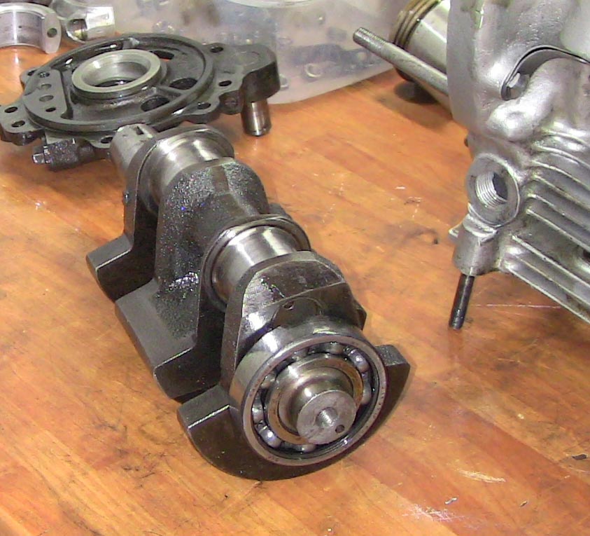
Worn front ball race.
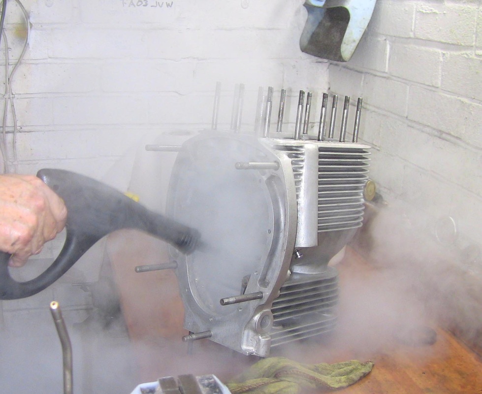
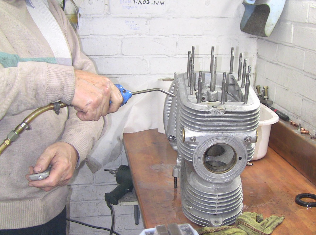
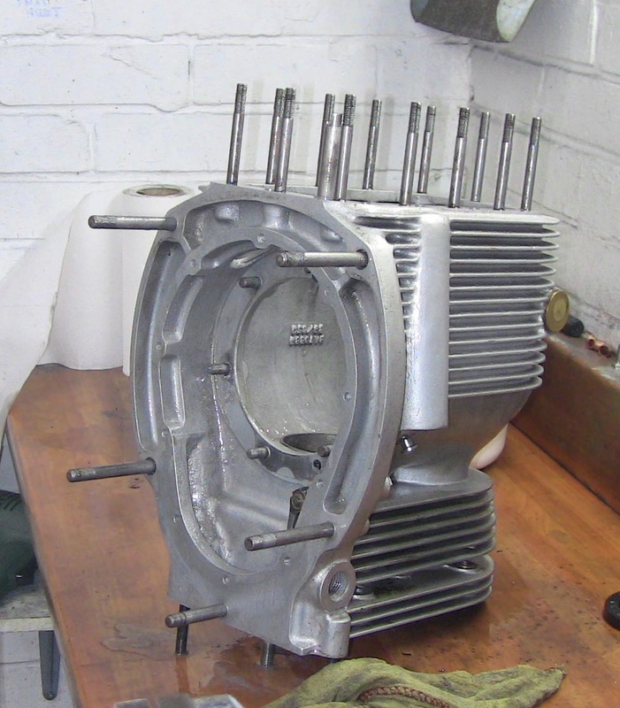
Cleaning the engine block.
I never have engines shot blasted with anything. The material used gets everywhere and before you know it the engine is wrecked. I use a cheap steam cleaner I bought out of the local cash convertors for 20 quid. I brush 'Jizer' or even better 'Gunk', still available in aerosol cans on the engine block. Repeated applications with the steamer and then blown dry with compressed air.
Next comes the crankshaft. Sometimes you have to drill a hole in the centre of the coreplug and wind in a stud extractor. New core plugs available from Stewart Engineering.
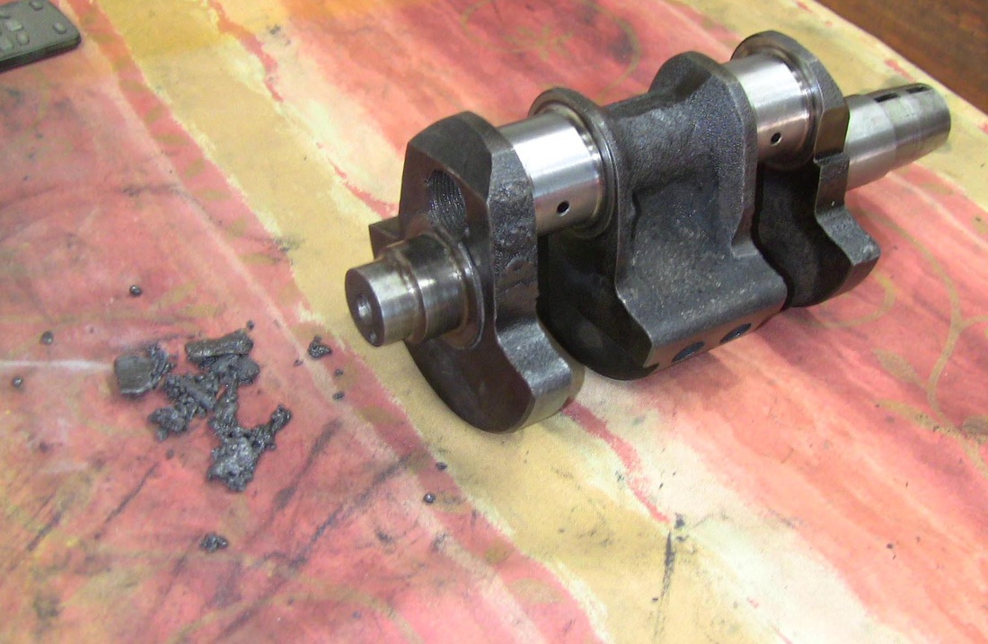
Picture above shows sludge removed from hollow crankshaft after core plug removed.
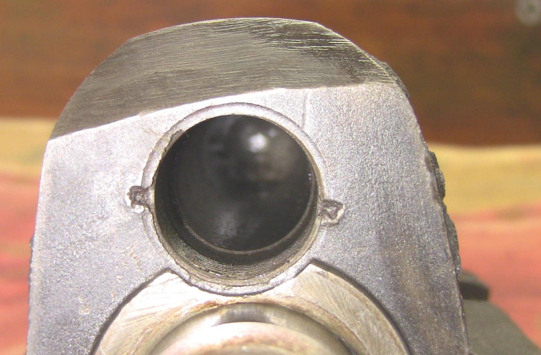
Picture below shows hollow crankshaft clean as a whistle.
Picture below shows hollow crankshaft clean as a whistle.
Everything is now clean.
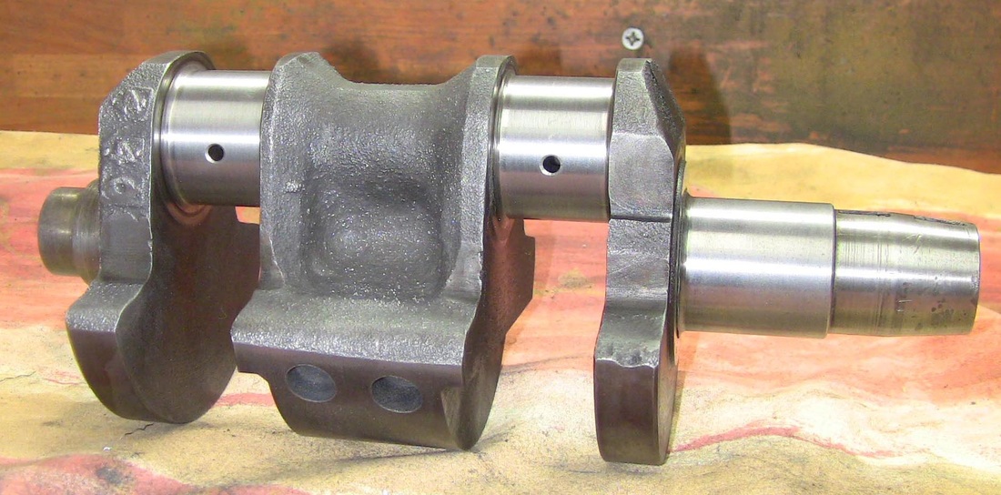
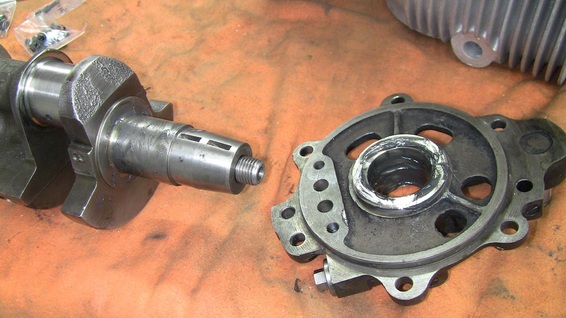
Crankshaft refurbished, good as new. This shows cleaned up rear main journal. This is really important to ensure oil pressure is maintained throughout crankshaft. The white metal main bearing and main journal have to be 'sized' so that a close tolerance fit is ensured. White metal is very soft but has very good bearing qualities.
I have this job done by a specialist engineering company listed in my recommended suppliers.
Below is shown the refurbished white metal rear main bearing.
Picture below shows crank main bearing and white metal main bearing liberally coated with graphite grease prior to assembly.
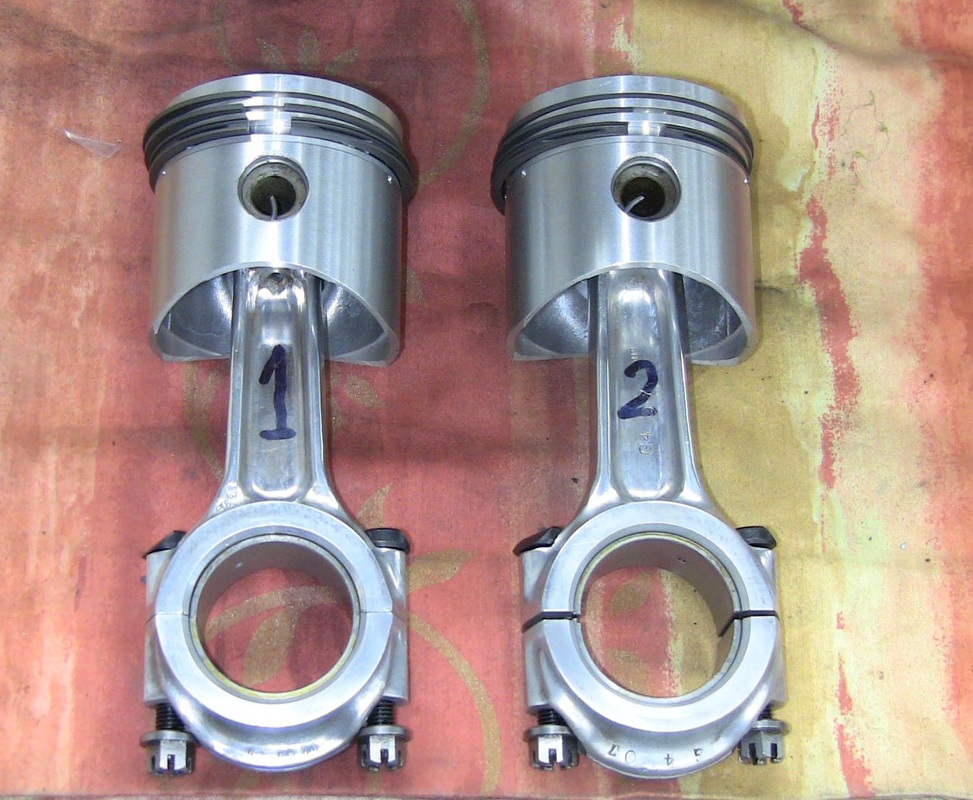
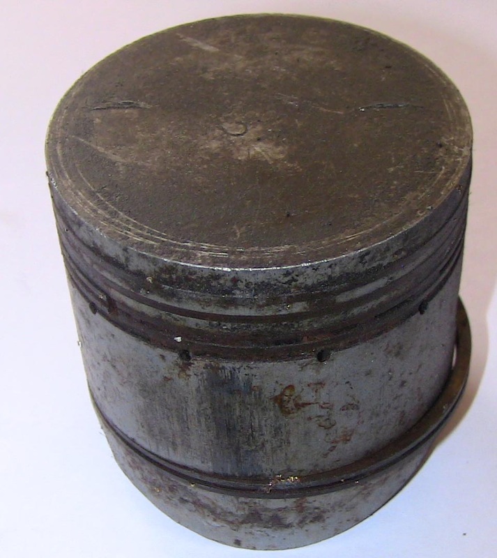
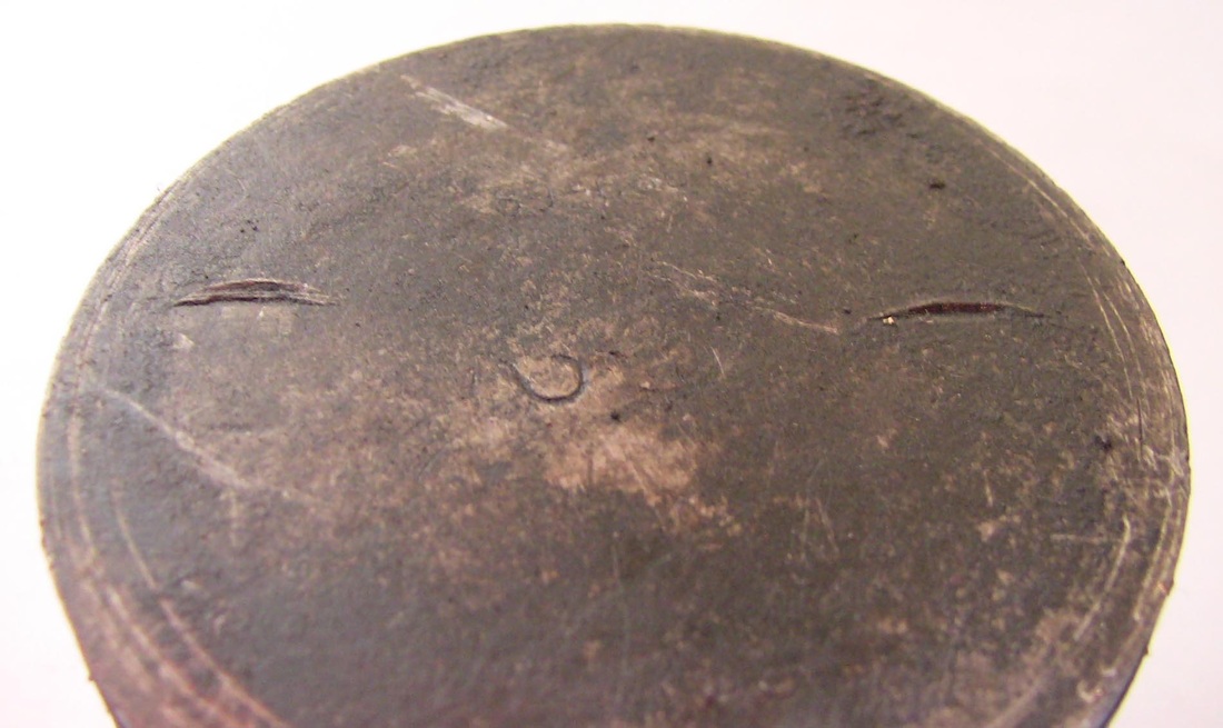
Australian pistons for the Sunbeam engine shown above.
These are flat topped as supplied by T and L Engineering of Bedford ( UK ). Now if your old pistons have witness marks to the valves hitting the crowns as shown in the pictures below of an old Sunbeam piston, the new pistons have to have valve cutouts machined into them.
This operation can be carried out by T and L Engineering at the same time as the cylinder block is being rebored.
The fact that the valves have touched the piston crown suggests that the head and block have been skimmed to flatten them. This is not normally a problem if it the first time this has to be done. I would suggest that if on examination of a warped and distorted cylinder head and block that needs more than a few thou machined off to true the surfaces to have the new pistons machined for valve cutouts.
The manual states 18 thou valve gap on the rocker arms, this is correct. Reducing the gap to compensate for worn camshaft lobes is not recommended.
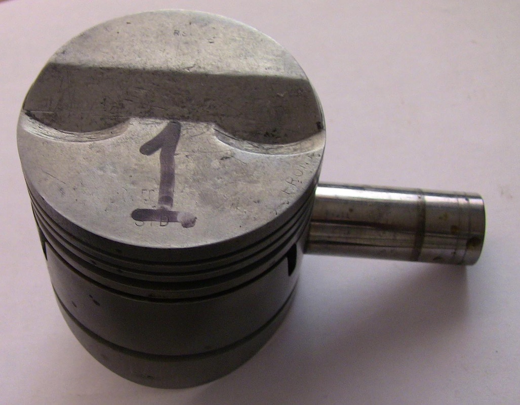
Bottom piston picture shows a Sunbeam genuine piston of 7 to 1 ratio with valve cutouts as standard.
These are flat topped as supplied by T and L Engineering of Bedford ( UK ). Now if your old pistons have witness marks to the valves hitting the crowns as shown in the pictures below of an old Sunbeam piston, the new pistons have to have valve cutouts machined into them.
This operation can be carried out by T and L Engineering at the same time as the cylinder block is being rebored.
The fact that the valves have touched the piston crown suggests that the head and block have been skimmed to flatten them. This is not normally a problem if it the first time this has to be done. I would suggest that if on examination of a warped and distorted cylinder head and block that needs more than a few thou machined off to true the surfaces to have the new pistons machined for valve cutouts.
The manual states 18 thou valve gap on the rocker arms, this is correct. Reducing the gap to compensate for worn camshaft lobes is not recommended.
Bottom piston picture shows a Sunbeam genuine piston of 7 to 1 ratio with valve cutouts as standard.
Timing Gears.
The half time pinion bush and spindle do wear and when they do the engine sounds noisy. Easily fixed when the engine is stripped for repair. The spindle tends to wear on the underside where the camchain pulls on it especially if the chain is adjusted over tight.
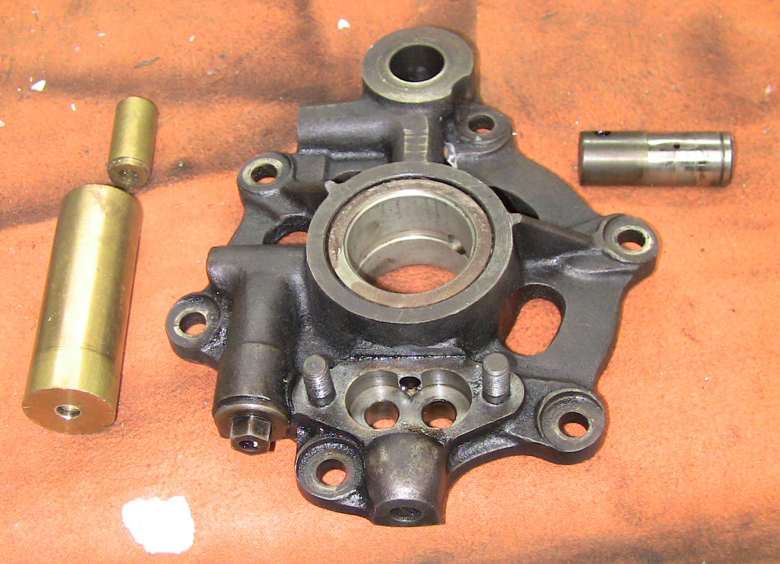
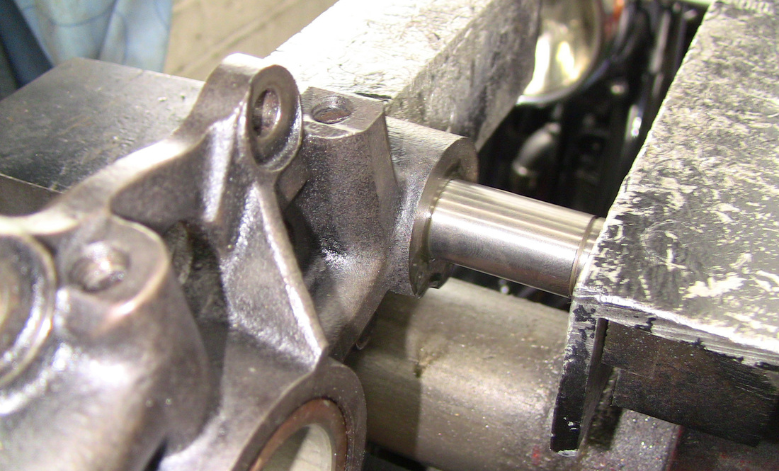
The above picture shows a two part brass tool I made which pushes the worn spindle out of the main bearing casting using a large vise. This is shown below squeezing in the new spindle ( note aluminium vise jaws. ). When fitting the new spindle the oil hole has to line up with the oilway in the casting. Test by squirting oil through the main bearing, oil should then emerge through hole in spindle.
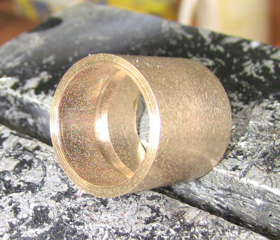
The bush for the half time pinion needs to have an oil groove machined in it, as shown below. This is to prevent it 'nipping up' on the spindle if the chain is overtight. My original bush as factory fitted had this oil groove fitted. I strongly recommend when replacing the bush that it has an oil groove machined in it.
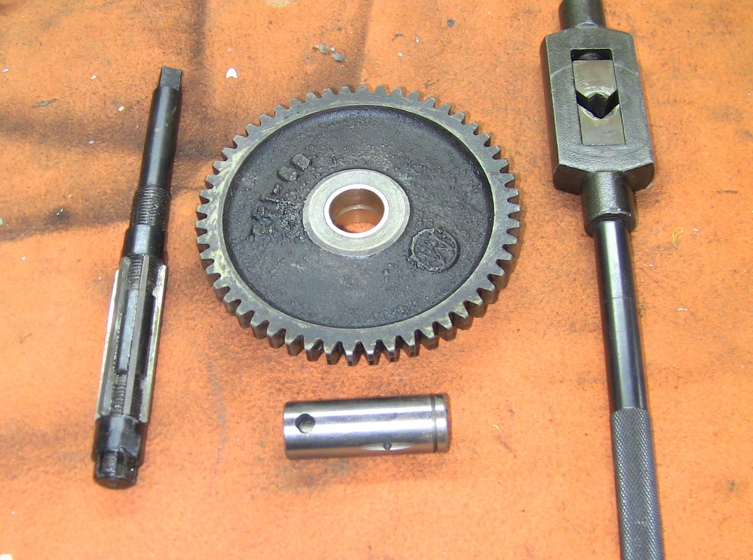
Picture below shows new bush fitted and ready to be reamed to size. The reamer is an internal expanding type. The size is 23/32nd to 25/32nd. Cost around seven quid from Tracy Tools at Dartmouth, Devon.
Picture below shows ream in action, take it very slow and only take the minimum cut at a time, always trying spindle in bush. Ream from both sides until spindle is a dead fit.
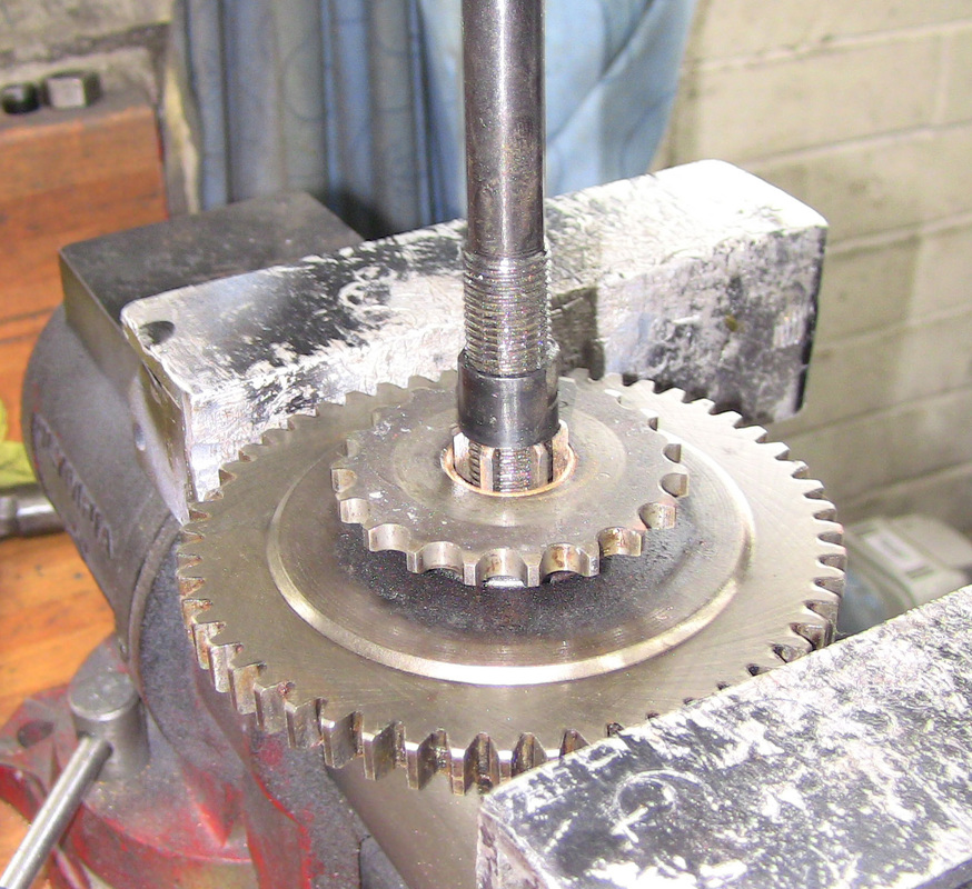
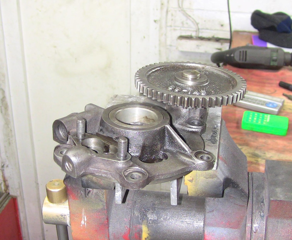
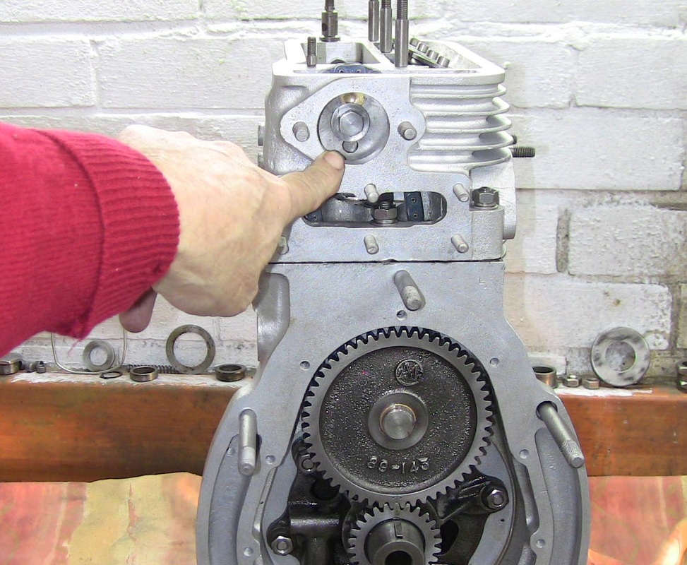
Above picture shows half time pinion fitted exactly onto spindle.
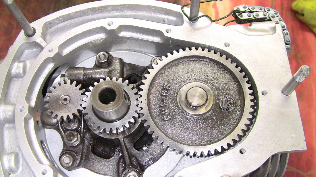
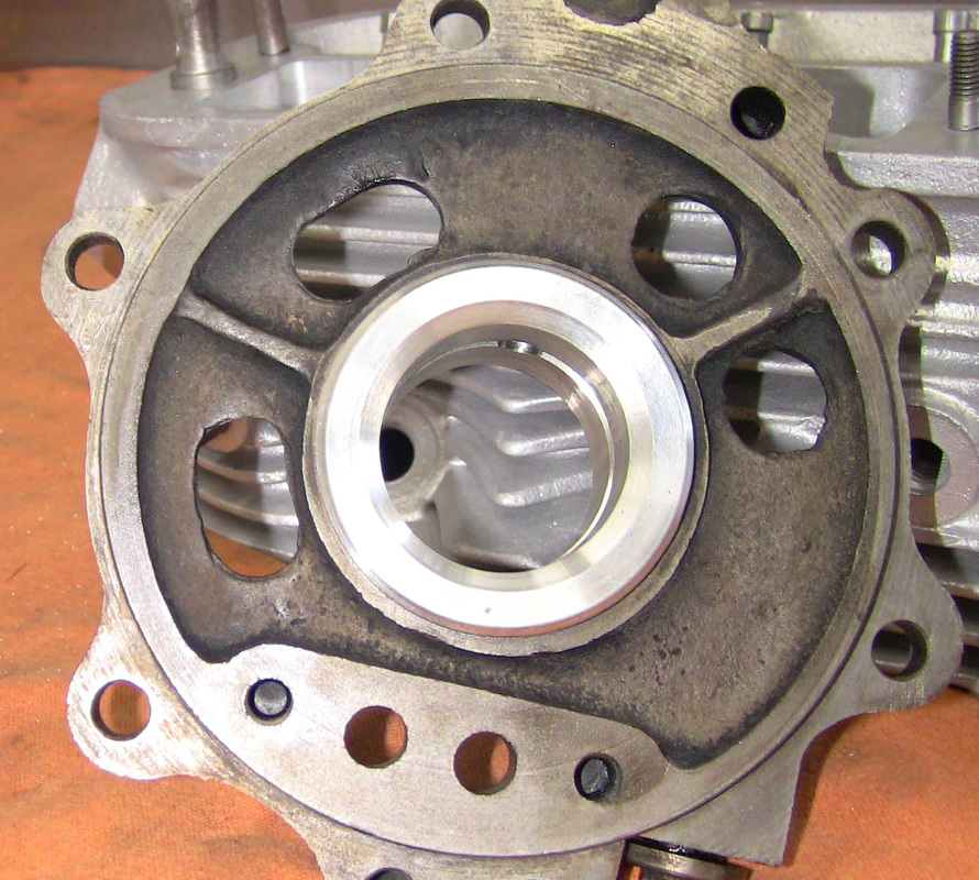
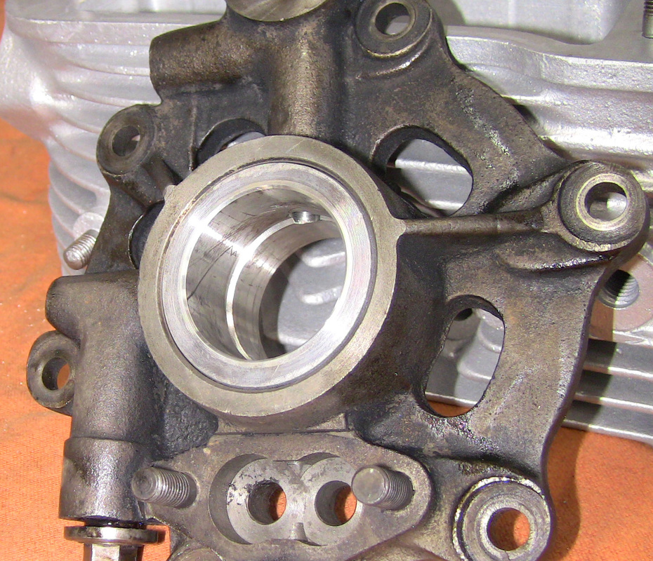
Back plate assembly fitted into engine case showing oil pump installed and timing marks aligned.
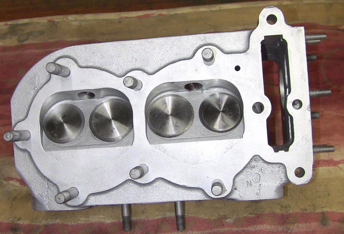
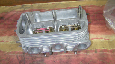
The Cylinder Head.
The Cylinder Head.
|
|
New hard unleaded valve seats fitted. New guides and valves.
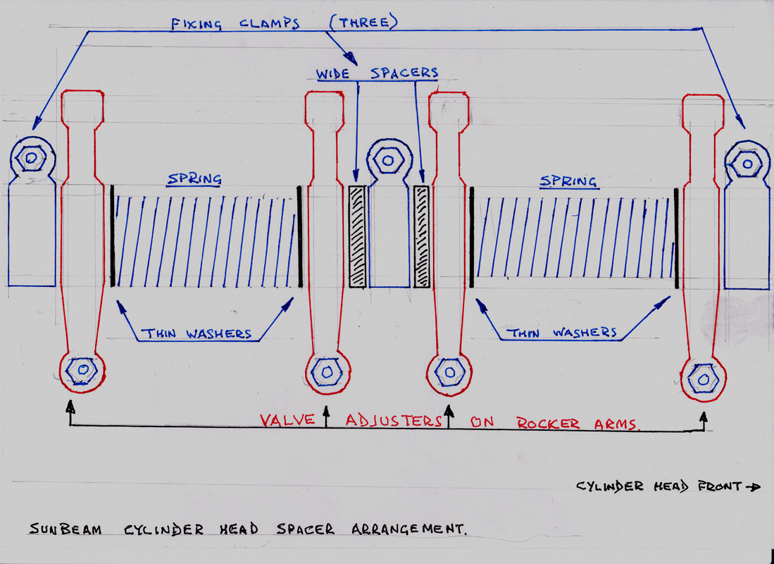
Above drawing shows spacers and washers on rocker shaft.
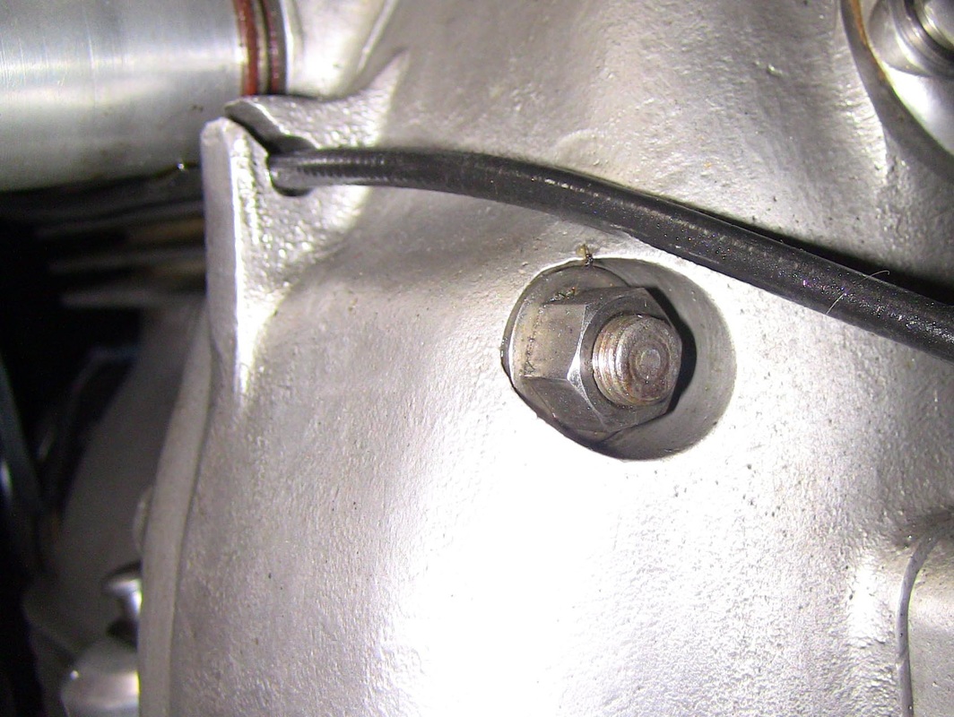
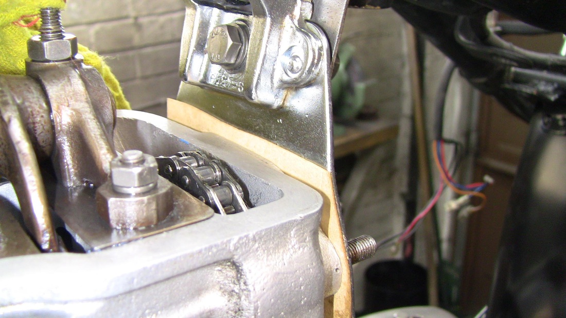
Timing marks aligned on crank and camchain sprocket in correct timing position with chain link horizontal, showing at top of cylinder head. The 3/8th nut holding down the cylinder head can be seen behind the camchain.
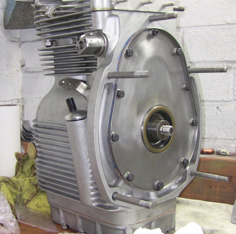
Backplate fitted with new cork gasket and oil seal, all ready for flywheel and clutch. A touch of blue Hylomar on the cork gasket holds it in place when assembling.
Top bolt has extended shank to stop camchain falling down.
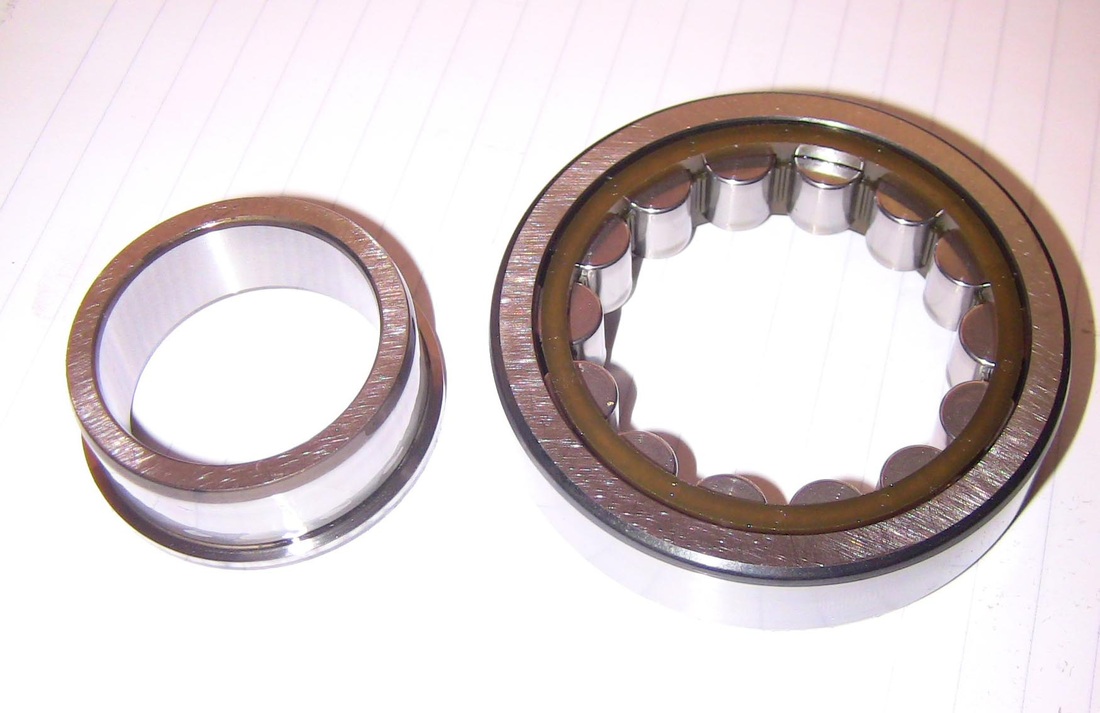
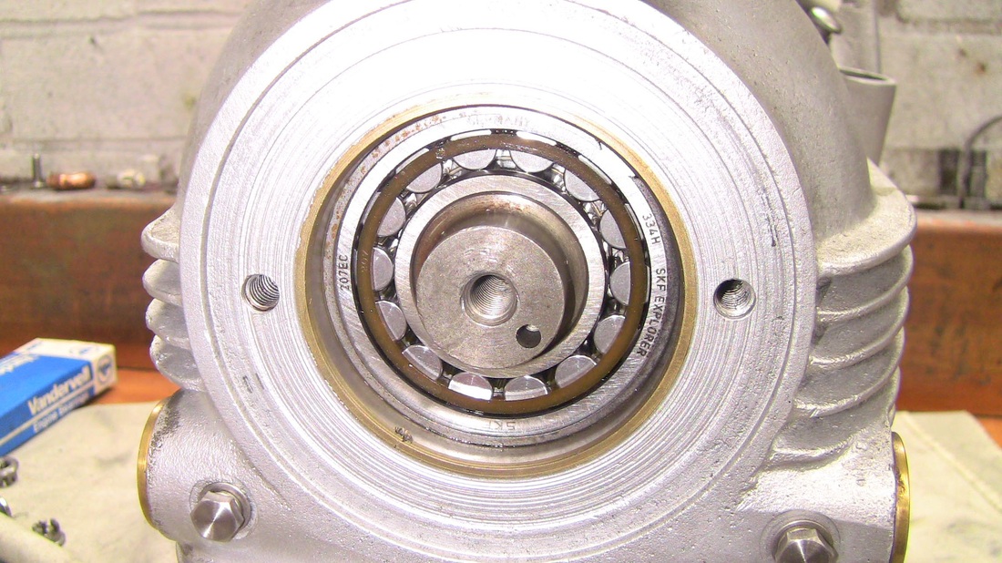
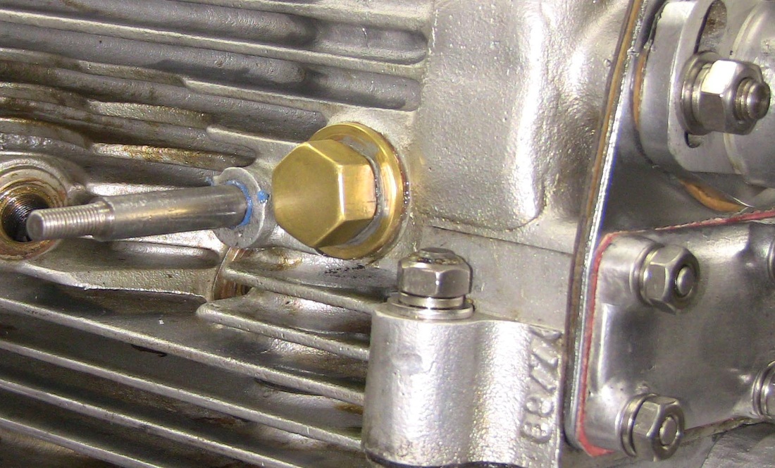
At the front I fitted a heavy duty roller bearing where the rollers are caged in the outer track. This makes setting the end float on the crank very simple. There are fourteen rollers in the bearing to carry the load. The bearing was obtained from Simply Bearings ( on the internet ) for around £40. Part number is NJ 207 ECP. SKF
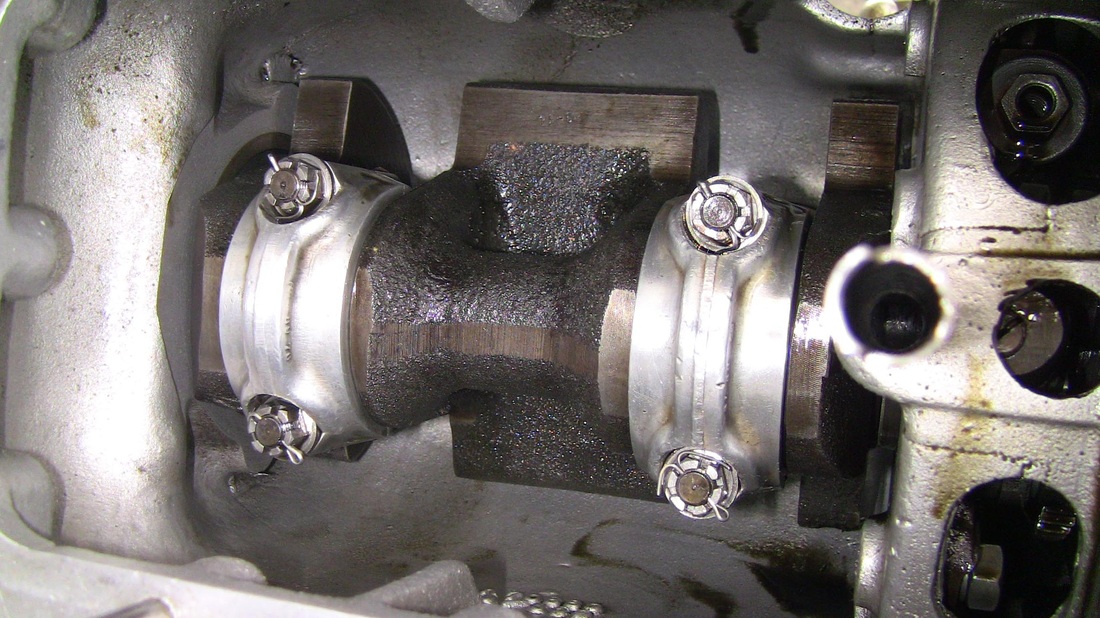
Above view showing stainless steel split pins in bigend bolts. Because of high rotational speed of crankshaft mild steel pins break up and end up stuck to magnetic drainplug. This should not result in any damage, if the bigend nuts are torqued to the right setting they will not come undone. The pins can be replaced with the engine in situ by using a mirror.
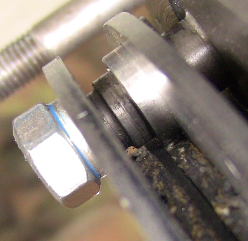
Tightening of clutch nuts.
First picture below shows assembly of clutch. The nuts have to be tightened so that the plate is hard up to the shoulder, in other words the picture below shows the outer plate not fully tightened up to shoulder of stud, the second picture below shows nut fully tightened up to shoulder of stud. This is correct. Do not worry if you have not fully tightened the nuts as they are easily accesible with a socket spanner through the timing inspection hatch on the gearbox bell housing.
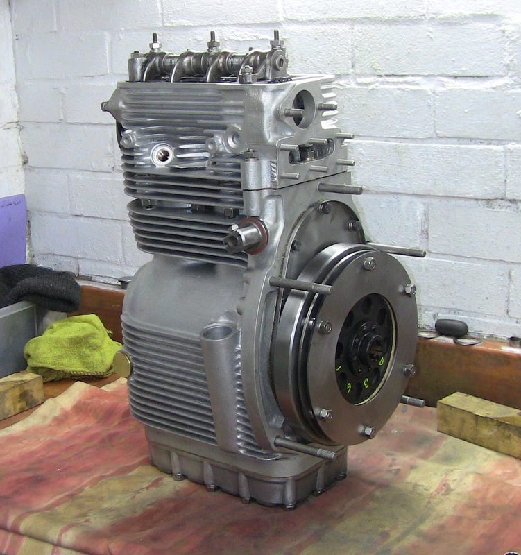
Finished engine with clutch installed.
The gearbox is held on with 3/8th BSF small hex nuts.
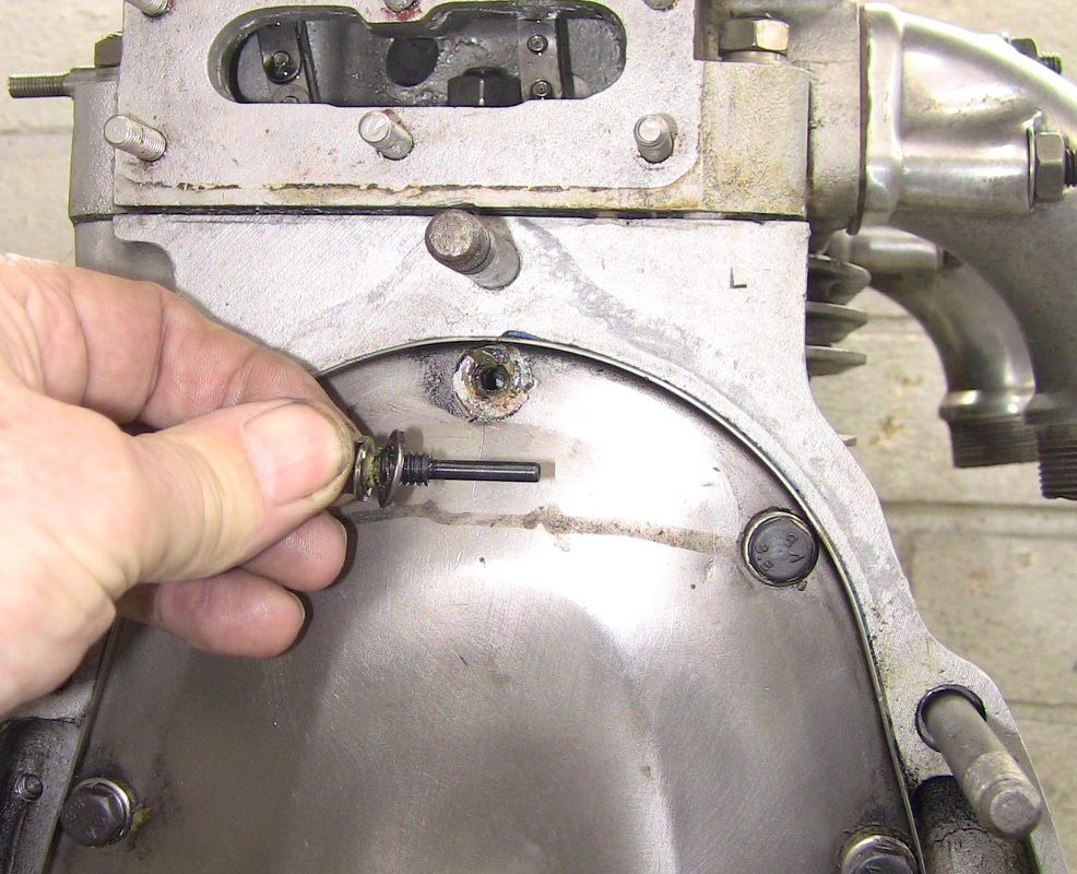
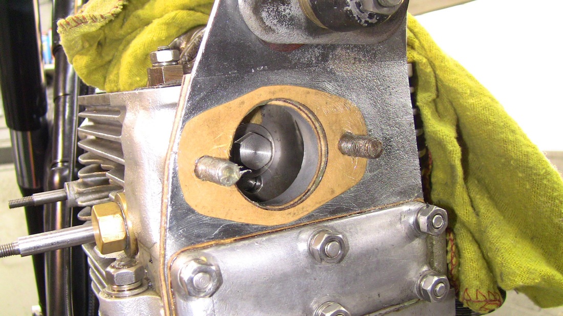
Fitting the engine damper plate.
|
Picture above shows damper plate mounted with a thick paper gasket.
Picture above shows thin paper distributor gasket.
|
|
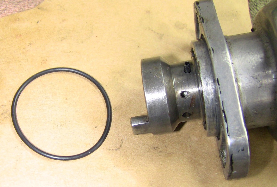
Picture above shows new O ring.
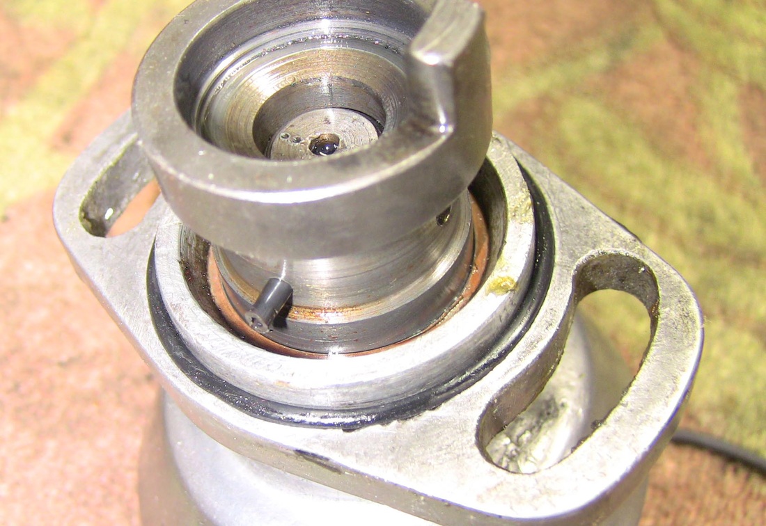
Picture above shows new O ring installed.
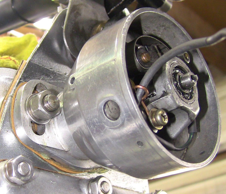
Picture above shows distributor installed. Note remachined face on adjustment slots.
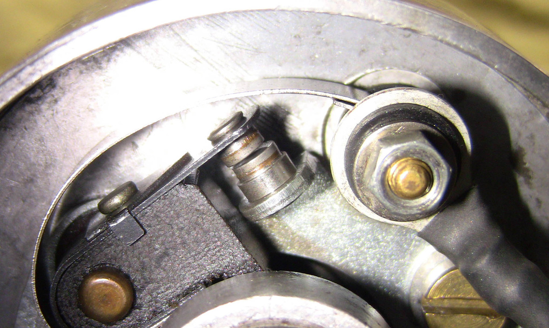
Points plate mounted with points at top. If oil seal fails oil will not affect points.
Points set at 5 thou, no wear after 4500 miles. Condensor eliminated.
Forget about dwell angles with electronic ignition using points assist. The points sole task is to switch the electronic ignition unit on and off. The ignition unit provide the 'oomph' for the coil faster and better than points and condenser ever can. This with neglible wear and improved long term timing of the spark.
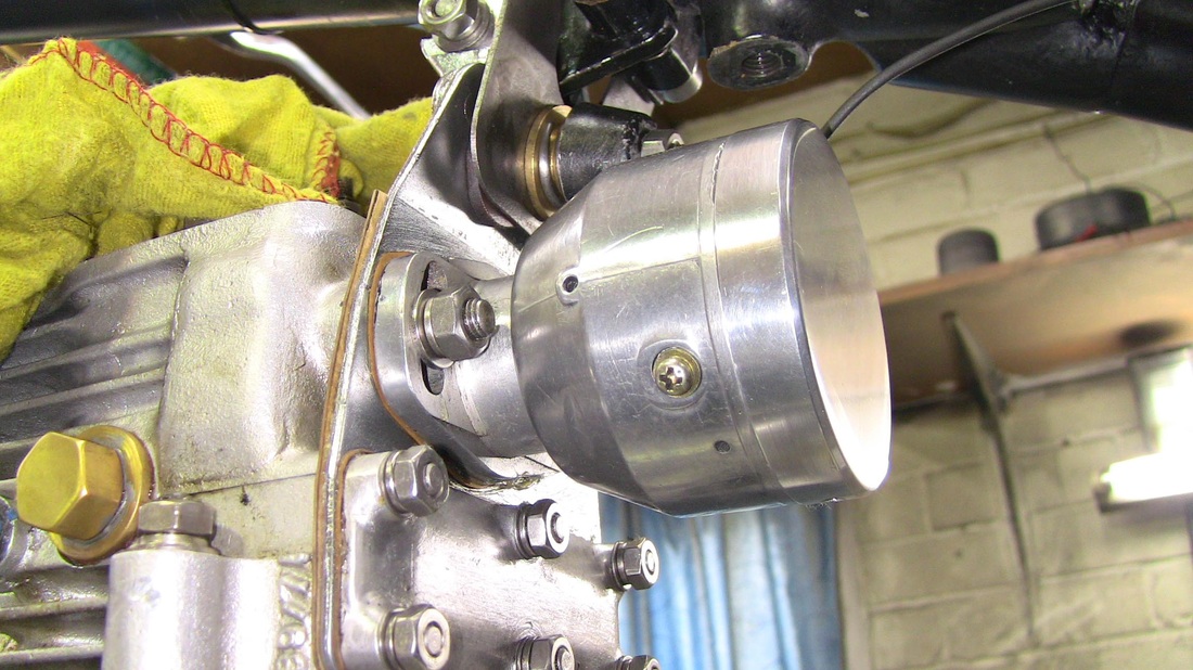
Picture below shows finished distributor with blanking cap installed for use with redundant spark ignition systems. Timing the distributor is described below.
Points set at 5 thou, no wear after 4500 miles. Condensor eliminated.
Forget about dwell angles with electronic ignition using points assist. The points sole task is to switch the electronic ignition unit on and off. The ignition unit provide the 'oomph' for the coil faster and better than points and condenser ever can. This with neglible wear and improved long term timing of the spark.
Picture below shows finished distributor with blanking cap installed for use with redundant spark ignition systems. Timing the distributor is described below.
Timing the distributor.
To ensure spot on timing I always engrave a marker line on the flywheel at the TOP DEAD CENTRE position. I also engrave a mark on the backplate again at TDC. This is shown in the picture below.
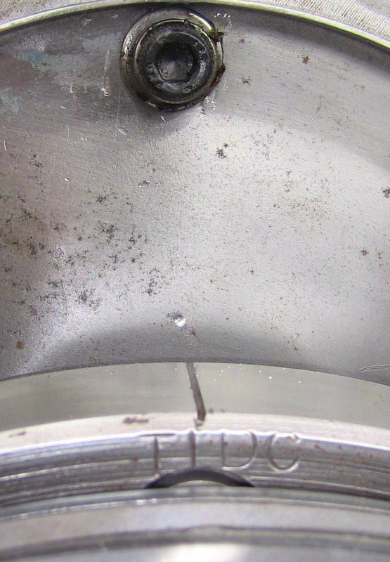
Close up of engraved dot on backplate. This is done with a dog tag engraver.
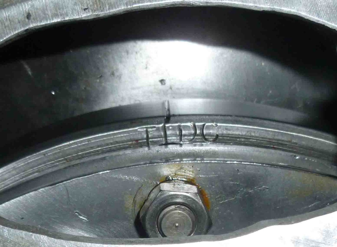
Picture above shows flywheel just approching TDC. I connect a digital test meter switched to OHMS to the distributor points. When the distributor and the flywheel are just on the point of changing the display I carefully nip up the distributor nuts watching the meter display, if necessary redoing the procedure until it is right.
----------------------------------------------------------------------------------
----------------------------------------------------------------------------------
PRIMING THE OIL PUMP.
Just to be on the safe side after rebuilding the engine I always prime the oil pump. I do this through the tapped hole for the oil pressure switch. I fill with oil using clean oil. Leave for a minute, then with the sparking plugs out smartly swing the kick start pedal two or three times and the oil should start to trickle back out. Either put back the oil pressure switch with a new sealing washer or in my case the blanking plug.