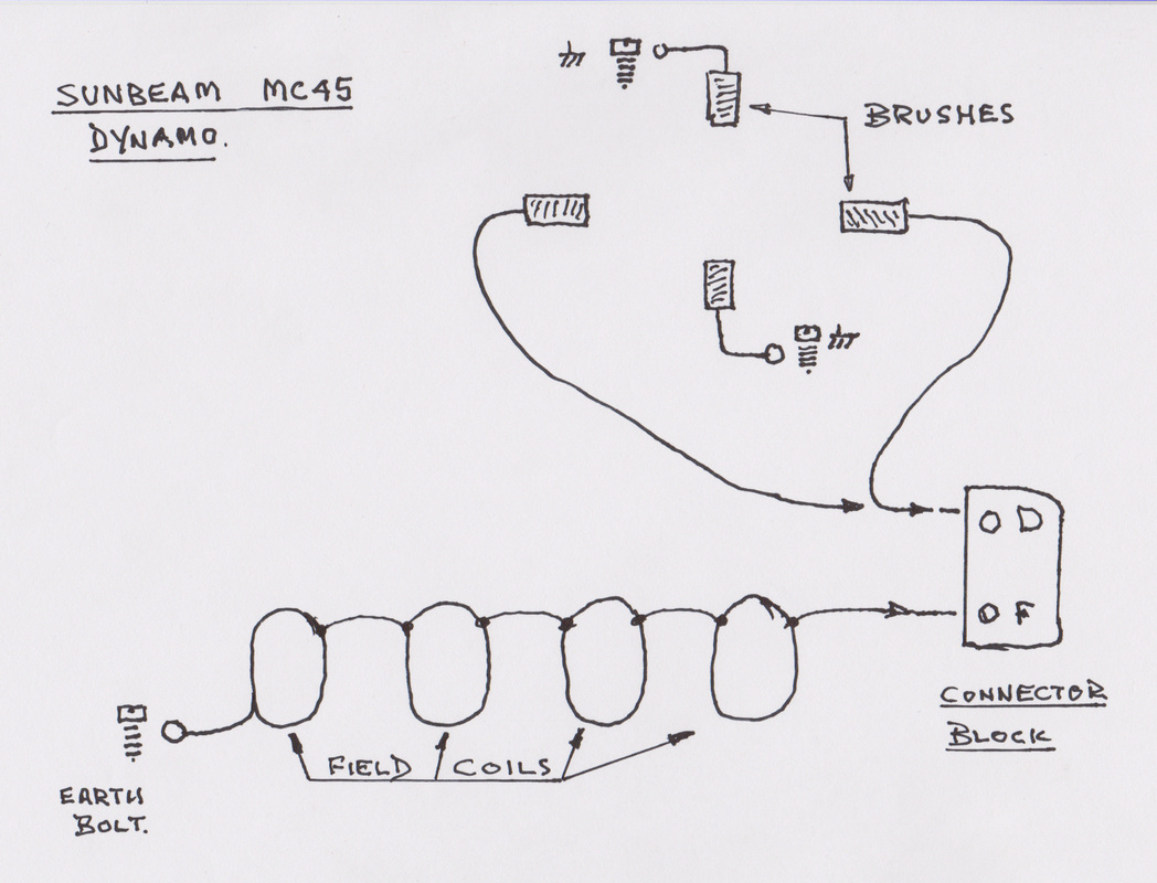
LUCAS MC45 DYNAMO
The Lucas MC45 dynamo is easy to strip and examine, The centre fixing bolt is left hand thread. The dynamo is long lasting and reliable. All parts are available for replacement, the armature is a service exchange from Stewart Engineering. The pictures show the dynamo body cleaned of all stains and rust.The four coils are prewired together and are terminated correctly for easy assembly.
The pole pieces are cleaned with a rotary wire brush. The four countersunk screws have a 60 degree taper.
( See picture at end of article. ) The screws should be mild steel. When assembling the pole pieces to the coils make sure the pole pieces are square to the dynamo body. Gradually tighten the screws. Use a touch of graphite grease on the threads and on the taper of the head. Try not to chip the screw heads by using a correctly fitting screwdriver. The screws I supply are slightly longer than the originals so the threaded holes in the pole pieces need to be tapped right through. I used two small G clamps to seat the pole pieces firmly to the body.
The carbon pickup brushes, two opposites are wired to the dynamo body while the remaining two go to the D terminal on the connector block. When the dynamo is finished and installed it will need magnetising. Link the F and D terminals together then if negative earth polarity is required momentarily touch a charged 12 volt battery across the dynamo, positive to the shorting link and negative to the dynamo body. Do this a couple of times, for positive earth reverse the battery polarity.
Apply two light coats of grey primer from a spray can, then two light coats of satin black also from a spray can. The dynamo does run hot being bolted to the engine, so the heat needs to be dissipated quickly, I would not recommend stove enameling the dynamo body. Also keeping the aluminium end cover polished will also help to get rid of the heat.
The dynamo like all dynamo's turns out direct current or dc. It does not need a rectifier unlike an alternator. The dynamo is very flexible in that it can be used with positive or negative earth. This is described above on how to magnetise a dynamo. Dynamo's need regulating as the voltage rises with revolutions per minute. This can be taken advantage of as the dynamo can be regulated to six volts or twelve volts with a modern solid state regulator.
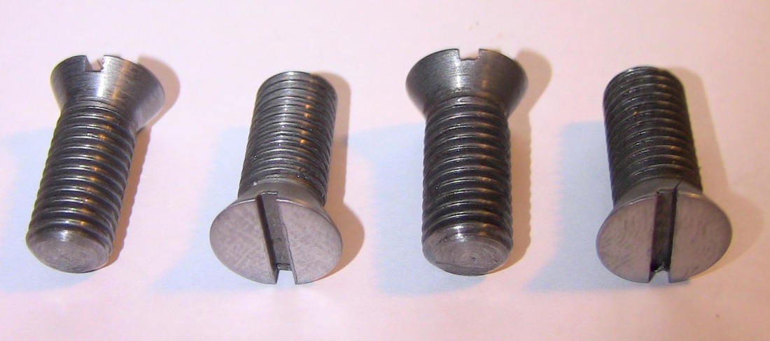
Dynamo bolts finished with 60 degree taper. They are available in 1/4 BSF or 5/16 BSF.
Please check thread diameter in pole piece.
Please check thread diameter in pole piece.