Redundant spark ignition. Plus further notes and pictures of the distributor cap and its fitting.
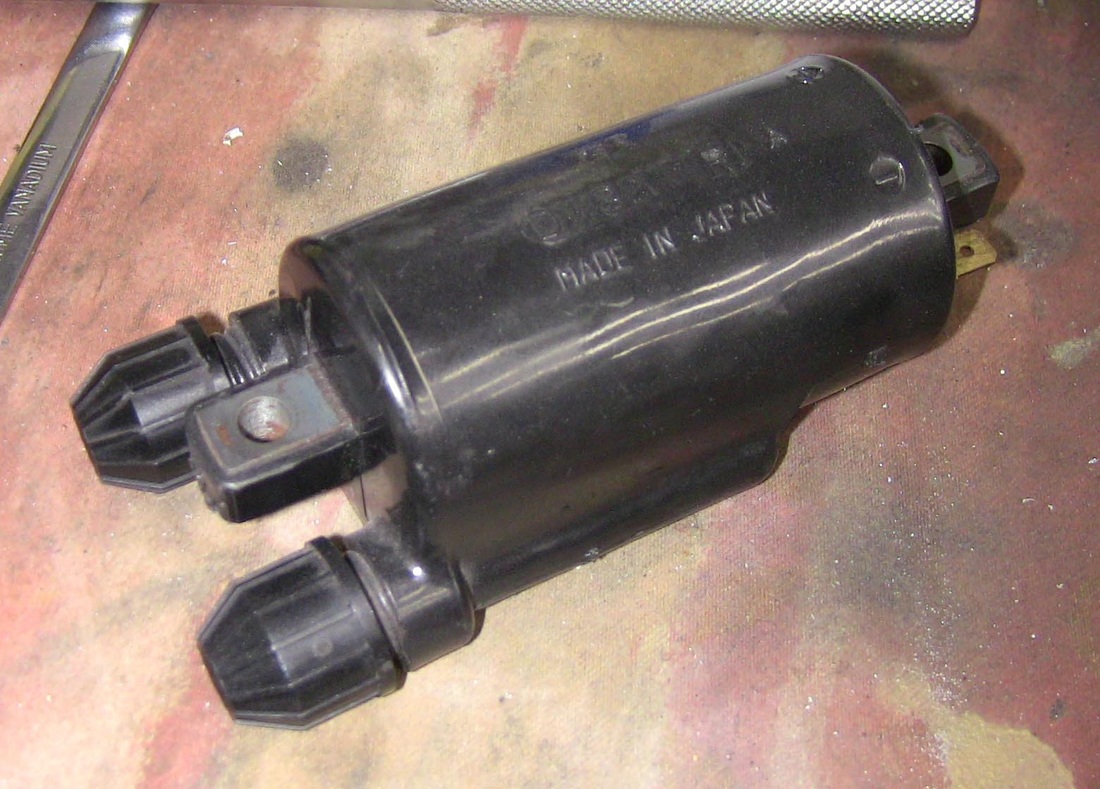
The 360 crankshaft employed in the Sunbeam engine lends itself to redundant spark ignition. Both pistons rise and fall together, this gives equal firing pulses. So if your distributor cap or rotor arm is on it's last legs, redundant spark ignition is the way to go. The distributor points becomes a switch only for the ignition system. A double ended coil is required to fire both plugs simultaneously. A Honda coil is shown below.
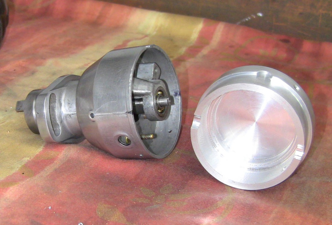
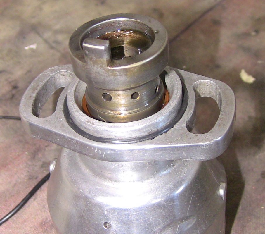
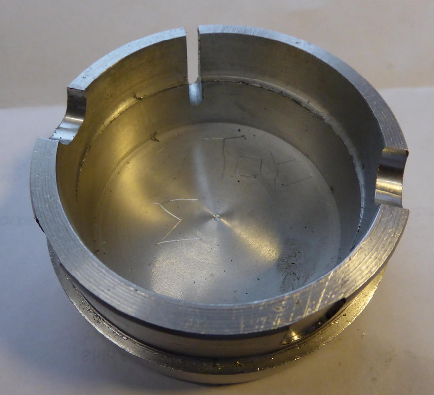
Distributor with blanking cap. Please note the distributor cap has a clearance eccentric machined in it. As shown below. This is to provide good clearance for points spring steel mechanism.
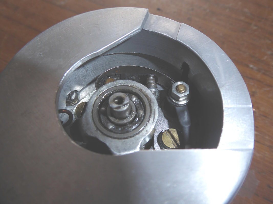
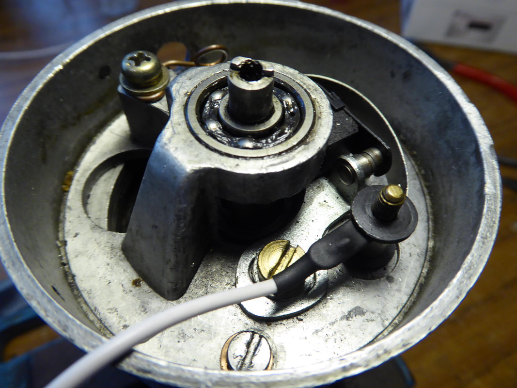
The two pictures above show a cutaway of the distributor cap showing points spring clearance and the white wire connection.
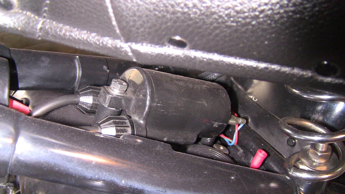
Coil mounted underneath seat.
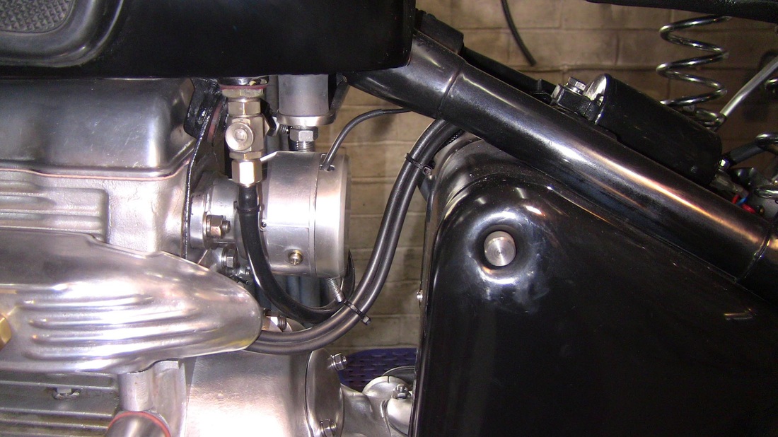
Distributor with blanking cap fitted.
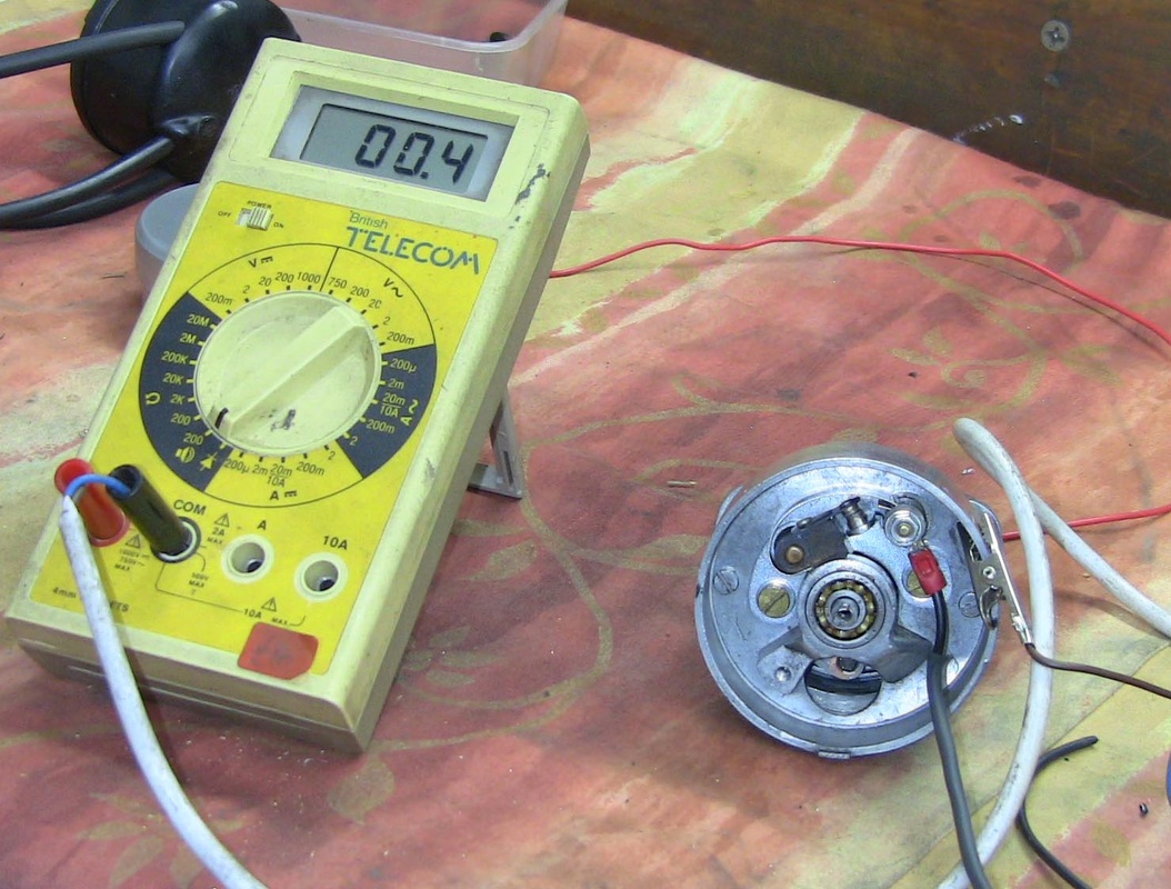
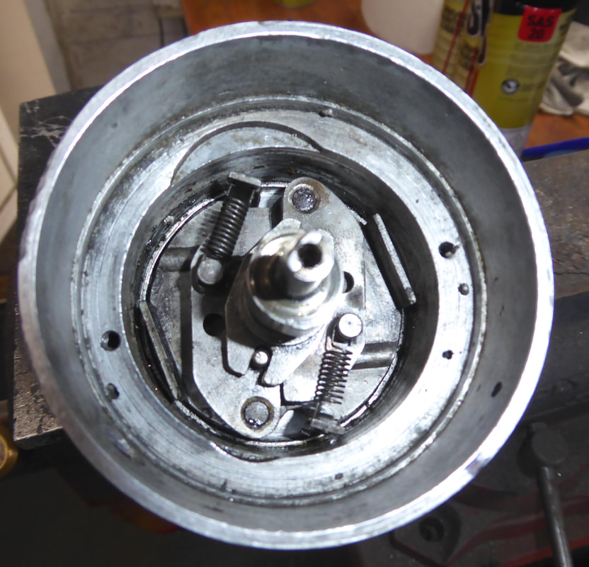
Points only, no condenser or rotor arm. Points plate rotated 180 degrees so that ignition points are at top away from any oil. Points gap set to 6 thou.
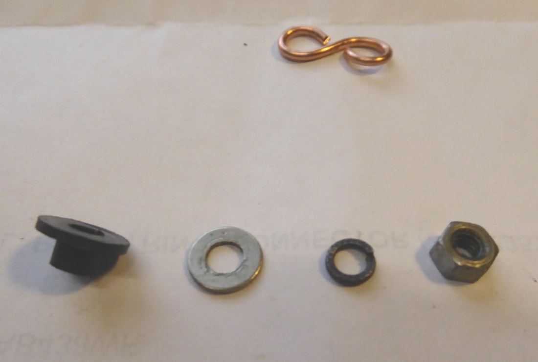
Below is shown the plastic tophat, 4BA nut and washers.The retaining loop is also shown along with sample white wire showing 5 mm ringtag.
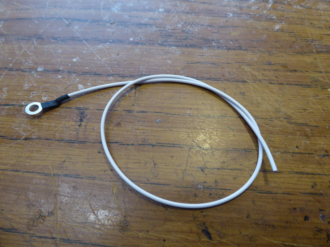
Shown above is the supplied white wire and ringtag fitted under the tophat .
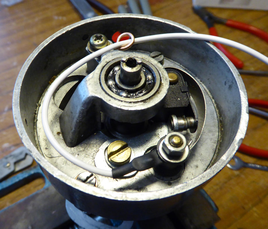
Shown above is the white wire installed with the small wire retainer installed ( This is supplied. )
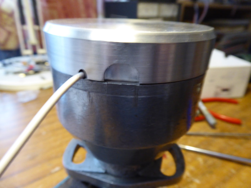
Carefully slide cap onto distributor body fitting the white wire into the machined slot, as shown above.
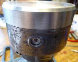
After fitting the cap line up the 4mm tapped hole with the hole vacated by the condenser. Now fit the supplied 4 mm cap screw and washer.