Modifications Page Three. On this page :
Cracked cambox covers.
How to fix cracked cambox covers.
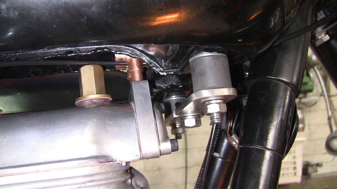
All cambox covers are cracked and bent, that is the flange is distorted due to the three centre bolts being tightened down to several tons of foot pounds of torque. First job is to flatten the flange. Any charity shop will have a mirror of the type that hung above Grandma's fireplace. These mirrors are wooden backed and very strong. A touch of fine grinding paste and patient rubbing will have the cambox flange good as new in no time. Now for the cracked bosses, I turned up three aluminium bosses. These were 1 inch in diameter by 3/8th inch thick with a 3/8th hole through the middle. I bolted these bosses to the top of the cambox and the local welder ( a bit too enthusiastic with the apparatus ) welded the bosses in place. I countersunk the holes underneath for clearance on the studs, I then machined the bosses to 1/4 inch thick. Then I turned my attention to the fixing nuts. I used 19 mm hex bar and machined these with a 3/8th spigot. I then made three brass washers and soft soldered them onto the nuts. A final turn on the lathe to true the brass washers completed the nuts. I made three soft washers as gaskets for the nuts. Engine top end now oil tight.
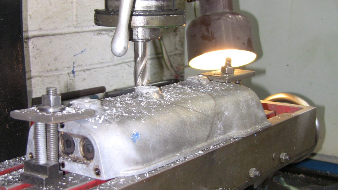
Milling the welded bosses.
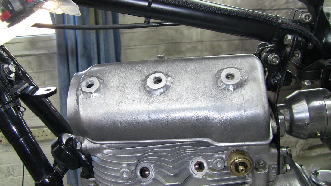
Completed bosses.
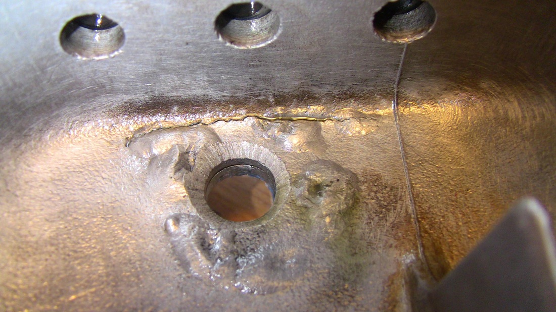
Repaired and countersunk fixing hole.